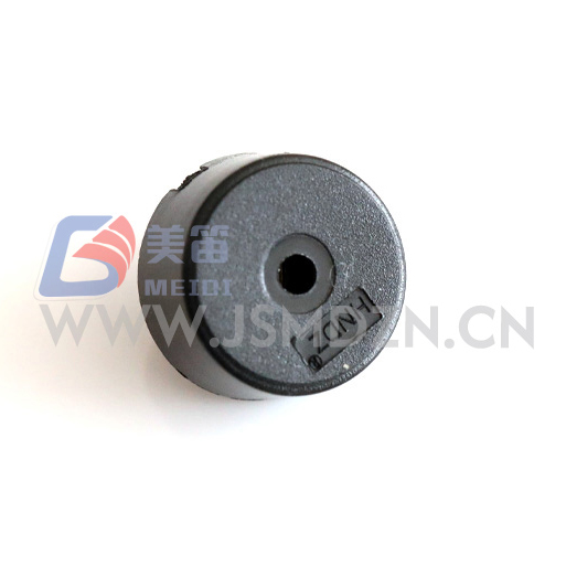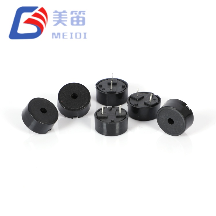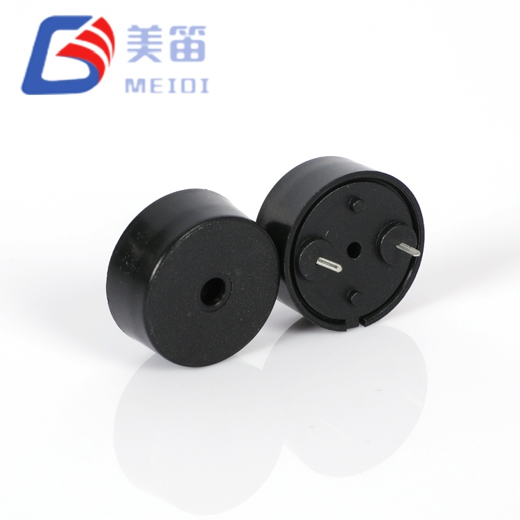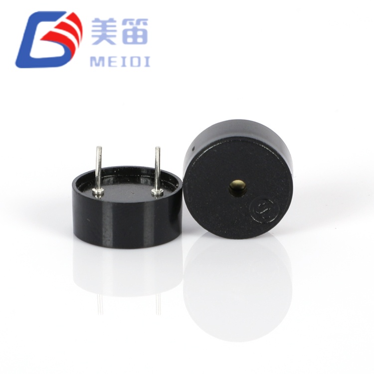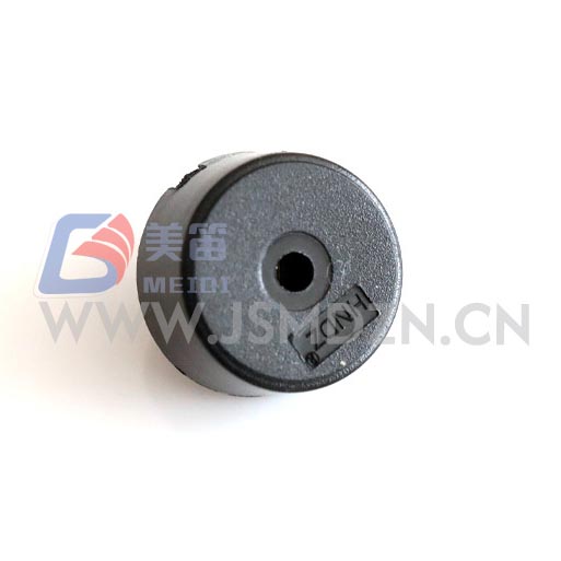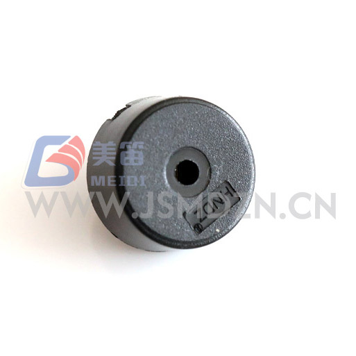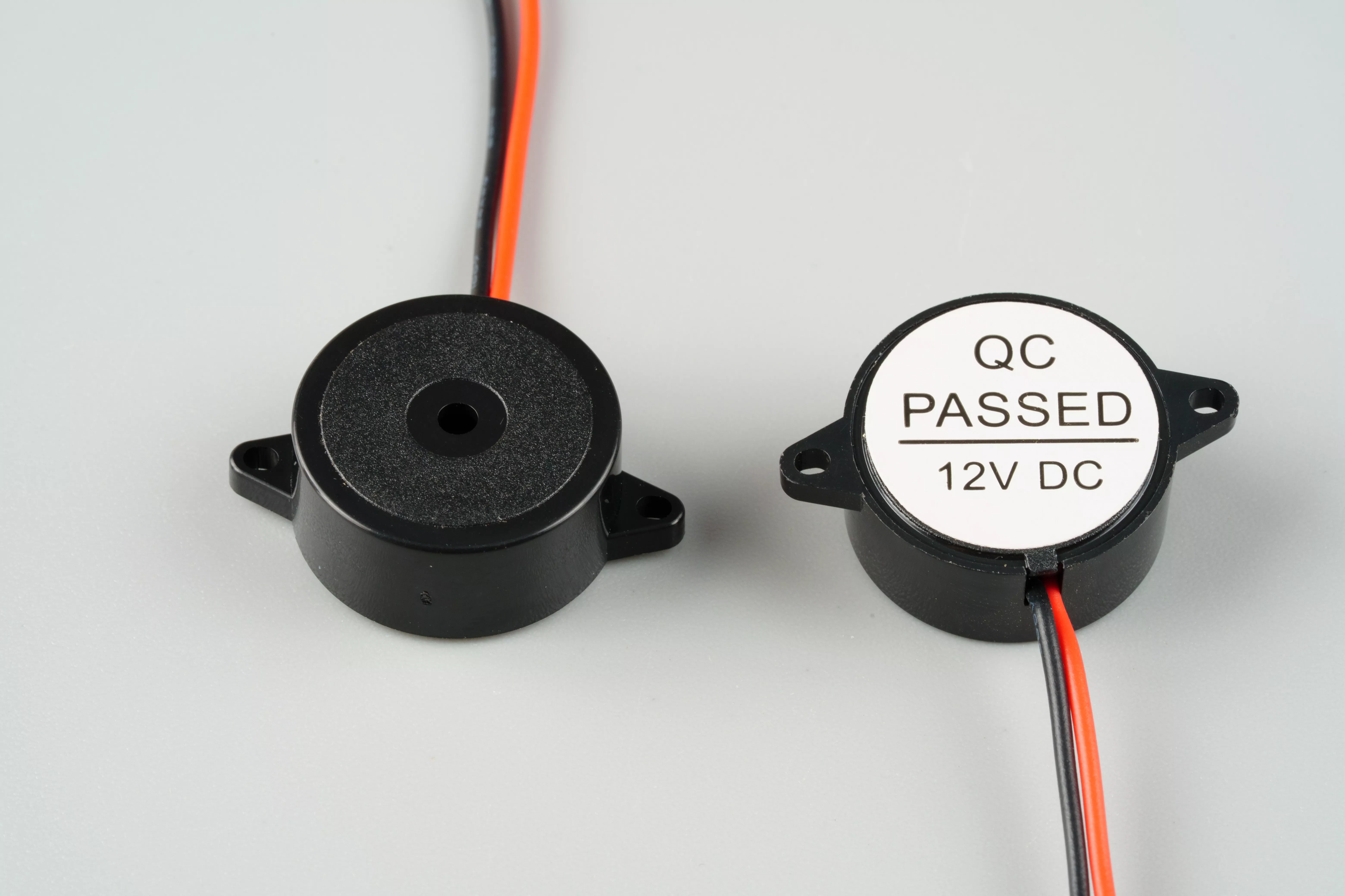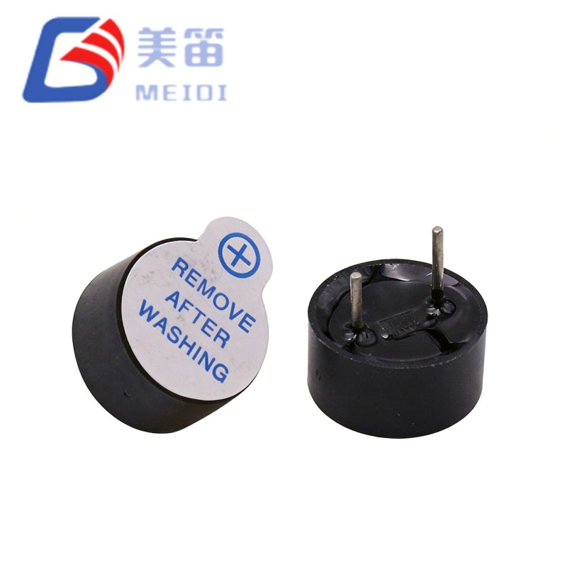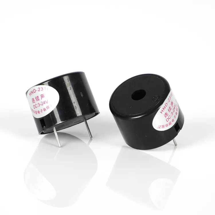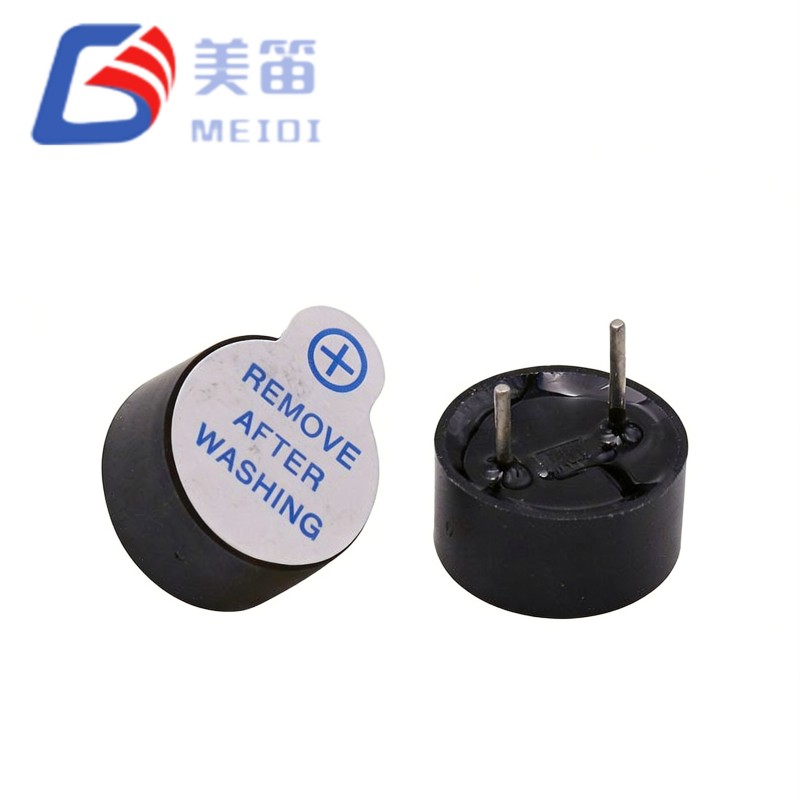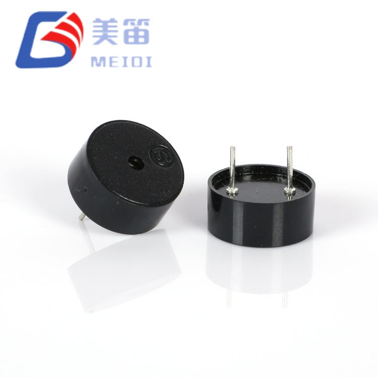
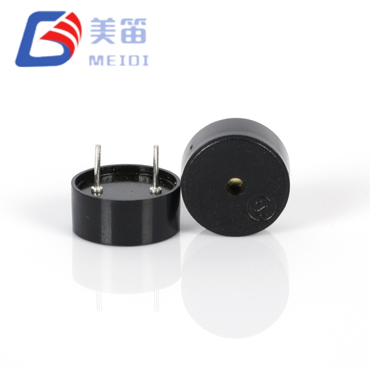
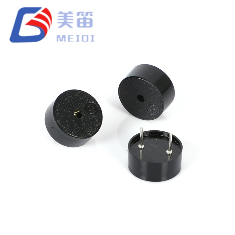
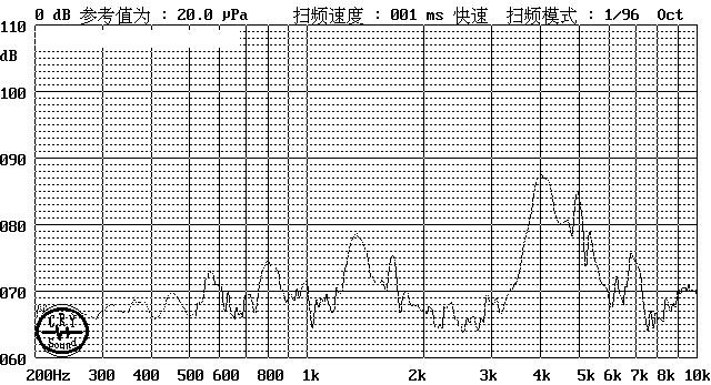
The Spring-Loaded Piezoelectric Passive Buzzer with Pogo Pin is a through‑hole piezoelectric passive buzzer engineered for applications where PCB z‑axis clearance is the primary mechanical constraint. At just 5.5 mm tall and 0.60 g, it offers the same acoustic output (83–86 dB at 4000 Hz) as taller 7.0 mm variants, while fitting into sub‑6 mm total assembly envelopes — including PCB thickness, solder joints, and housing clearance.
Manufactured in MEIDI’s ISO‑9001 certified Jiangsu facility, this component leverages a precisely tuned ceramic diaphragm and optimised internal cavity to maintain resonant efficiency despite the reduced height. Its 1–30 V ultra‑wide operating range eliminates the need for voltage‑specific SKUs, simplifying BOM management across 3.3 V, 5 V, 12 V, and 24 V product lines. With measured current consumption of just 0.63–0.78 mA at 5 Vp‑p, it delivers a 40‑to‑60× reduction in power draw compared to electromagnetic alternatives, making it ideal for battery‑powered wearables, portable medical devices, and IoT sensors.
The Spring-Loaded Piezoelectric Passive Buzzer with Pogo Pin is a passive piezoelectric transducer requiring external AC excitation — typically a 4000 Hz square wave from a microcontroller PWM output, timer, or dedicated piezo driver IC. As a passive device, it grants designers full control over tone patterns, frequency modulation, and duty‑cycle‑based volume adjustment, capabilities unavailable with fixed‑frequency active buzzers.
The 5.5 mm height represents a 21% reduction versus the 7.0 mm HNR‑1207 PA6.5, yet acoustic performance remains identical: sample measurements confirm 83–86 dB at 4000 Hz and 5 Vp‑p. This is achieved through refined ceramic element geometry and internal cavity tuning that preserves Helmholtz resonance efficiency within a thinner housing. The 12 nF nominal capacitance (measured 11.7–14.2 nF) is slightly higher than the 10 nF of taller variants, translating to a marginal increase in drive current (0.63–0.78 mA vs. 0.45–0.54 mA) — both figures remain sub‑milliampere and negligible for battery budgeting.
The 1–30 V operating range provides exceptional voltage elasticity: the same component works flawlessly on 3.3 V logic rails, 5 V USB‑powered devices, 12 V automotive accessory circuits, and 24 V industrial control buses. No voltage regulation, series resistors, or active clamping are required. This flexibility reduces inventory complexity and simplifies global supply chain management.
Through‑hole polarized pins ensure correct orientation during automated assembly and provide robust mechanical retention under vibration and shock. The black PBT housing (UL94 V‑0) withstands wave soldering at 260 °C and manual rework at 350 °C, supporting both high‑volume production and field repair.
5.5 mm ultra‑slim profile – 21% height reduction compared to 7.0 mm alternatives; enables sub‑6 mm total z‑axis assemblies including PCB and solder
Acoustic performance parity – 83–86 dB at 4000 Hz matches thicker variants; no SPL penalty for slim form factor
1–30 V ultra‑wide operating range – single SKU replaces voltage‑specific buzzers across 3.3 V, 5 V, 12 V, and 24 V systems
12 nF capacitive load – direct MCU GPIO drive in most applications; slightly higher capacitance than 10 nF variants for marginally louder output at same voltage
0.60 g ultra‑light mass – 9% lighter than 0.66 g alternatives; minimises inertial loading in wearable and portable designs
Through‑hole polarized mounting – mechanical retention and polarity protection in industrial and automotive installations
| Parameter | Value | Test Conditions |
| Product Type | Piezoelectric Passive Buzzer | — |
| Rated Voltage | 5 V (Vp‑p) | Square wave, 4000 Hz |
| Operating Voltage | 1 – 30 V (Vp‑p) | Continuous |
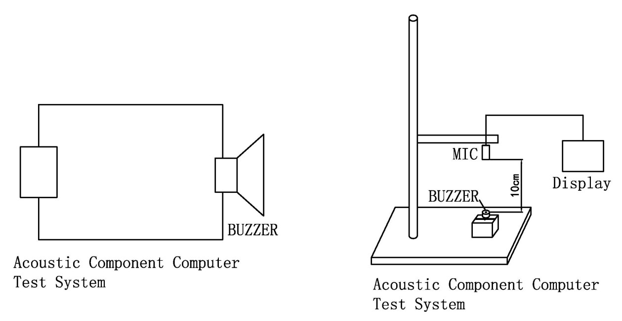
| Sound Output | ≥ 80 dB | At 5 Vp‑p, 4000 Hz, 10 cm |
| Resonant Frequency | 4000 ± 500 Hz | At rated voltage |
| Current Consumption | ≤ 10 mA | At 5 Vp‑p, 4000 Hz; measured 0.63–0.78 mA |
| Capacitance | 12 ± 40% nF | At 1 kHz, 25 ℃; measured 11.7–14.2 nF |
| Operating Temperature | -20 ℃ ~ +70 ℃ | Continuous |
| Storage Temperature | -30 ℃ ~ +80 ℃ | Non‑operating |
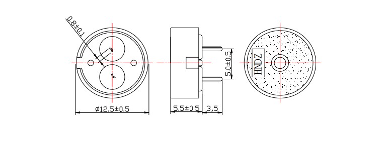
| Dimensions (Dia × H) | 12.5 × 5.5 mm | Body only |
| Weight | 0.60 ± 0.2 g | Typical |
| Housing Material | Black PBT | UL94 V‑0 |
| Mounting Type | Through‑hole | Polarised pins |
| Soldering Temperature (Wave) | 260 ± 5 ℃ | 4–6 s, recommended |
| Soldering Temperature (Manual) | 350 ± 10 ℃ | 2–5 s, recommended |
| Design Parameter | HNR‑1207 PA6.5 (7.0 mm) | HNR‑1255 PA5.0 (5.5 mm) | Impact |
| Total z‑axis envelope | ≥ 8.5 mm with solder joint | ≤ 7.0 mm with solder joint | Enables sub‑7 mm assemblies |
| PCB‑to‑housing clearance | Tight in 8 mm designs | Comfortable in 7 mm designs | Expands compatible enclosure pool |
| Weight | 0.66 g | 0.60 g | 9% mass reduction for wearable applications |
| Capacitance | 10 nF | 12 nF | Marginally higher drive current; marginally louder at same voltage |
| SPL at 5 Vp‑p | 83–86 dB | 83–86 dB | No acoustic penalty for slim profile |
| Current at 5 Vp‑p | 0.45–0.54 mA | 0.63–0.78 mA | Both sub‑milliampere; both negligible vs. electromagnetic |
The 5.5 mm height is achieved through optimised internal cavity geometry and ceramic element thinning without reducing diaphragm effective area. For designers currently using 7.0 mm piezo buzzers with ≥1.5 mm clearance above the housing, the HNR‑1255 PA5.0 provides a drop‑in slim alternative with identical acoustic output and marginally higher capacitive load. This allows existing PCB layouts to accommodate a thinner component without electrical or acoustic redesign.
Wearable health devices – fitness tracker goal alerts, smartwatch notification tones, and hearable device pairing chimes where 6 mm total thickness is the wearable limit
Ultra‑thin IoT sensor nodes – environmental threshold warnings, tamper alerts, and connectivity status tones in sub‑10 mm total device thickness
Portable medical instruments – digital thermometer fever alerts, pulse oximeter limit tones, and portable ECG completion beeps in pocket‑sized devices
Smart card and token devices – transaction confirmation tones, PIN entry feedback, and battery‑low warnings in credit‑card‑form‑factor security devices
Automotive 12 V/24 V interior modules – seatbelt reminders, key‑in‑ignition chimes, and diagnostic tool feedback without voltage regulator overhead
Industrial 24 V control panels – fault indication, cycle‑completion tones, and limit‑switch alerts in PLC and relay‑logic systems
| Design Challenge | HNR‑1255 PA5.0 Solution |
| Z‑axis clearance ≤ 6 mm | 5.5 mm body height fits sub‑7 mm total assemblies including PCB and solder |
| Weight budget < 1 g in wearable | 0.60 g mass meets strict constraints without acoustic compromise |
| Multi‑voltage product consolidation | Single 1–30 V SKU replaces 3.3 V, 5 V, 12 V, and 24 V specific buzzers |
| No spare MCU pins for dedicated driver | 12 nF load drives directly from PWM‑capable GPIO; no transistor or IC required |
| EMC‑sensitive medical/RF environment | Piezoelectric actuation generates zero magnetic field; no ECG/EEG interference risk |
The HNR‑1255 PA5.0 addresses a specific mechanical constraint: the 5.5 mm height threshold. Many wearable, portable, and ultra‑compact IoT enclosures specify maximum 6–7 mm internal clearance above the PCB. Standard 7.0 mm piezo buzzers exceed this envelope when solder joint height (0.5–1.0 mm) and housing rib clearance (0.5 mm) are included. The HNR‑1255 PA5.0 resolves this with 1.5 mm of headroom to spare, allowing designers to maintain acoustic performance without enlarging the enclosure.
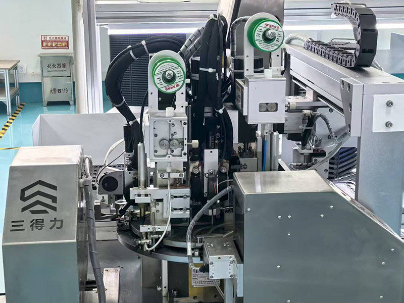
MEIDI produces the HNR‑1255 PA5.0 on dedicated piezoelectric assembly lines with automated ceramic pressing, electrode firing, and housing encapsulation. Our Jiangsu manufacturing base operates under ISO 9001:2015 quality management, with statistical process control at every stage – from raw material inspection to final acoustic verification.




Each production lot undergoes comprehensive qualification:
Capacitance 100% test – 12 nF ±40% verification at 1 kHz; measured range 11.7–14.2 nF ensures consistent driver matching
Resonant frequency sampling – 4000 Hz ±12.5% statistical verification; typical measured range 3900–4080 Hz
SPL batch verification – ≥80 dB minimum at 5 Vp‑p, 4000 Hz; sample range 83–86 dB confirms acoustic consistency
Current consumption validation – ≤10 mA maximum; measured 0.63–0.78 mA confirms sub‑milliampere efficiency
High‑temperature storage – 48 hours at +80 ± 2 ℃; parameter recovery after 2‑hour ambient stabilisation
Low‑temperature storage – 48 hours at -30 ± 2 ℃; verified activation at 1 V minimum
Thermal shock cycling – 5 cycles between -30 ℃ and +80 ℃ with 30‑minute dwell per extreme
Mechanical stress validation – sinusoidal vibration (10–55 Hz, 1.0 mm amplitude, XYZ axes, 0.5 hours cumulative) and 75 cm free‑fall drop onto 10 mm hardwood (3 impacts)
Humidity resistance – 48 hours at 50 ± 5 ℃ / 90–95% RH followed by 2‑hour recovery and electrical characterisation
Solder heat resistance – 250 ± 5 ℃ for 10 ± 0.5 seconds with 2.0 mm body‑to‑solder clearance
All components are RoHS, REACH, and UL94 V‑0 compliant. Lot code markings on each unit enable 10‑year traceability to production date, test data, and raw material certificates.
Q1: How does the 5.5 mm height affect acoustic output compared to the 7.0 mm HNR‑1207 PA6.5?
Acoustic output is equivalent. Both models deliver 83–86 dB at 4000 Hz and 5 Vp‑p. The HNR‑1255 PA5.0 achieves this through optimised internal cavity geometry and ceramic element tuning that maintains resonant efficiency despite the reduced height. The trade‑off is a slightly higher capacitance (12 nF vs. 10 nF) and marginally increased current draw (0.63–0.78 mA vs. 0.45–0.54 mA) – both still sub‑milliampere and negligible in practice. For designs where 7.0 mm fits, either model performs identically. For sub‑6 mm z‑axis constraints, only the 5.5 mm variant qualifies.
Q2: Can the HNR‑1255 PA5.0 replace the HNR‑1207 PA6.5 in an existing design without circuit modification?
Yes, with minor verification. Both share identical 12.5 mm diameter, 1–30 V range, 4000 Hz resonance, and through‑hole pin configuration. The 12 nF capacitance (vs. 10 nF) increases drive current by approximately 20% at the same voltage and frequency – from 0.5 mA to 0.6 mA typical. This is well within the capability of any MCU GPIO or driver circuit already designed for the HNR‑1207. Verify PCB keepout zones: the 5.5 mm height may reduce required z‑axis clearance, potentially allowing denser component stacking above the buzzer.
Q3: What is the minimum drive voltage for audible output in a 3.3 V coin‑cell design?
Approximately 1.5–2.0 Vp‑p produces faint but perceptible output in quiet environments. At 3.3 Vp‑p and 4000 Hz, expect 70–75 dB – adequate for proximity alerts, button feedback, and status tones in consumer devices. The ≥80 dB specification is validated at 5 Vp‑p; 3.3 V operation yields proportionally lower SPL. For battery‑critical designs, the sub‑milliampere draw means even a CR2032 coin cell (220 mAh) sustains 300 000+ hours of intermittent tone operation.
Q4: How does the 12 nF capacitance affect driver circuit selection compared to 10 nF alternatives?
At 4000 Hz, the capacitive reactance is approximately 3.3 kΩ for 12 nF (vs. 4.0 kΩ for 10 nF). This marginally higher load current is still well within standard MCU GPIO sourcing limits (typically 8–20 mA). For dedicated piezo driver ICs, the 12 nF load is comfortably within specification. The higher capacitance can actually be advantageous: at the same drive voltage, slightly more energy transfers to the ceramic element, contributing to the acoustic output parity with taller variants despite the reduced cavity volume.
Q5: Is the HNR‑1255 PA5.0 suitable for continuous‑tone 24 V industrial applications?
Yes, with appropriate drive circuit design. The capacitive nature means current remains self‑limiting by reactance – approximately 1.8 mA RMS at 24 Vp‑p and 4000 Hz. However, a series damping resistor (100–330 Ω) is recommended to suppress ringing and protect the driving transistor from reactive load transients. Ensure the drive circuit withstands 24 V levels; standard 3.3 V or 5 V MCU pins require a level‑shifting MOSFET or optocoupler. For continuous‑tone duty, the negligible current draw produces minimal driver heating even at 24 V.
Q6: Can this buzzer be used in high‑humidity environments such as marine or outdoor applications?
The standard HNR‑1255 PA5.0 is not hermetically sealed and is rated for 90–95% RH non‑condensing environments per the humidity resistance test (48 h at 50 °C / 95% RH). For continuous outdoor or marine exposure, MEIDI offers conformal coating or encapsulation as a custom option. Contact our engineering team to discuss ingress protection requirements and available modifications.
For drive circuit application notes, slim‑profile enclosure integration guidelines, PWM configuration examples, or volume pricing across the HNR piezo passive buzzer family, contact MEIDI Engineering Support.
MEIDI applications engineering typically responds within one business day with PCB keepout drawings, 3D STEP files, and volume pricing for multi‑SKU consolidation programs.
Address
No.6, Wenlin Road, Chenbao Town, Xinghua City, Jiangsu Province, China
Tel