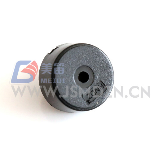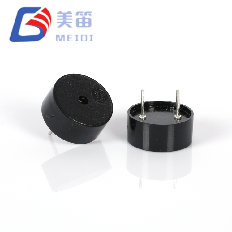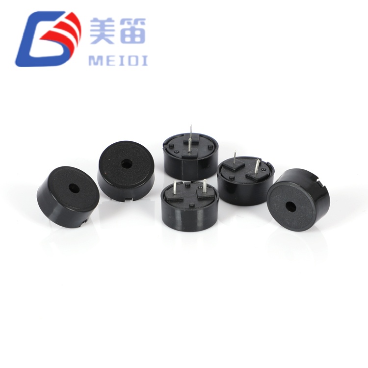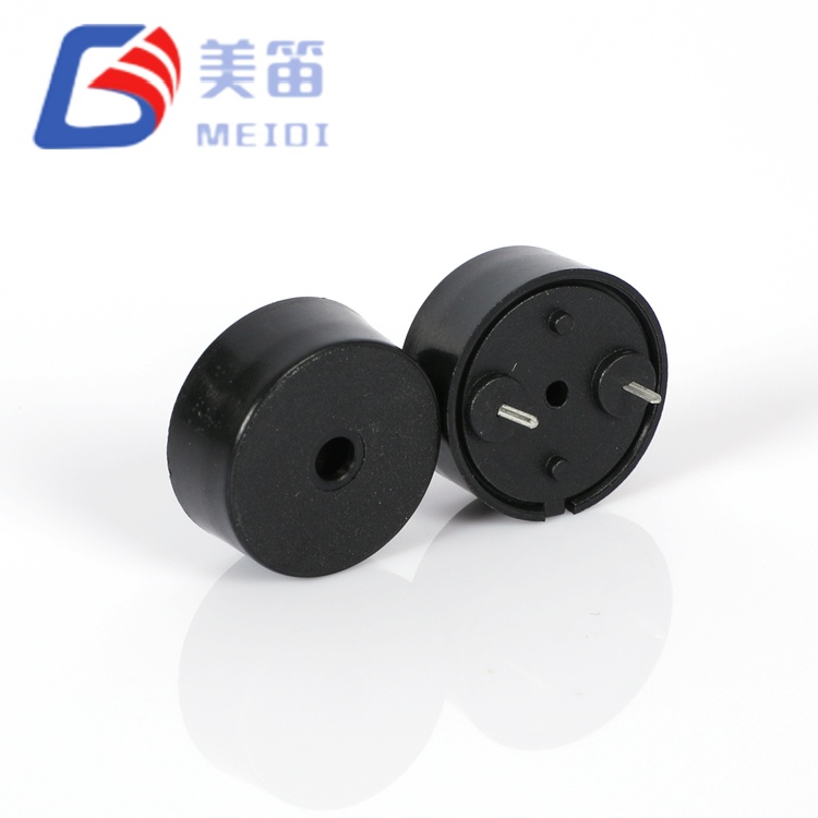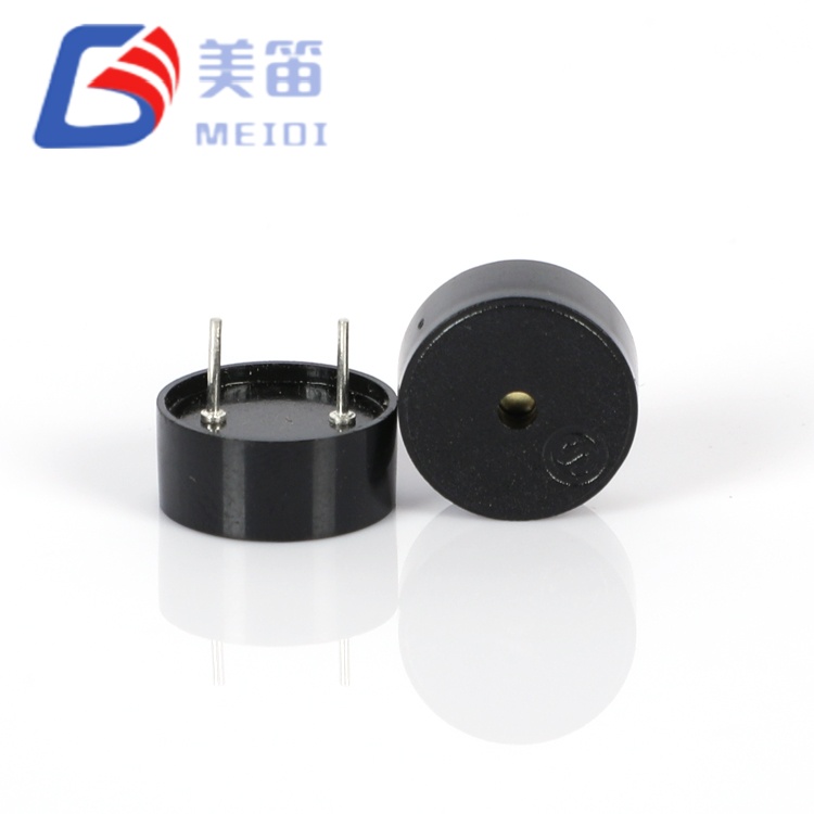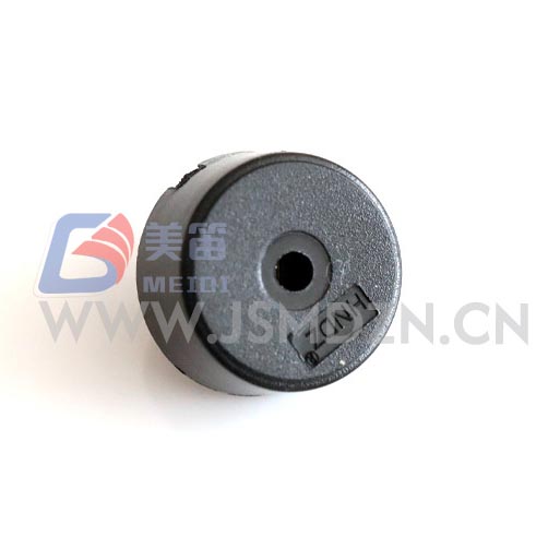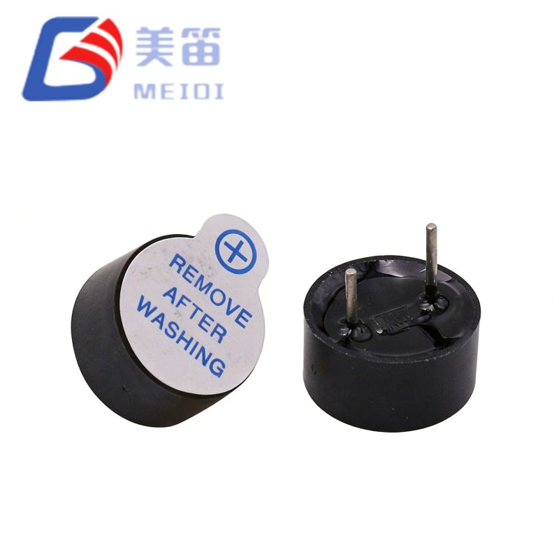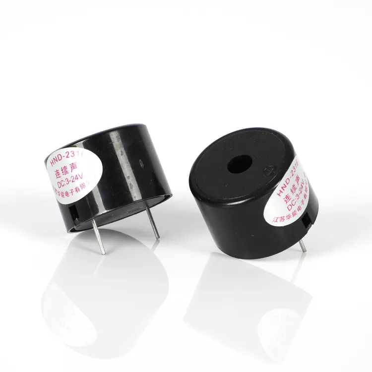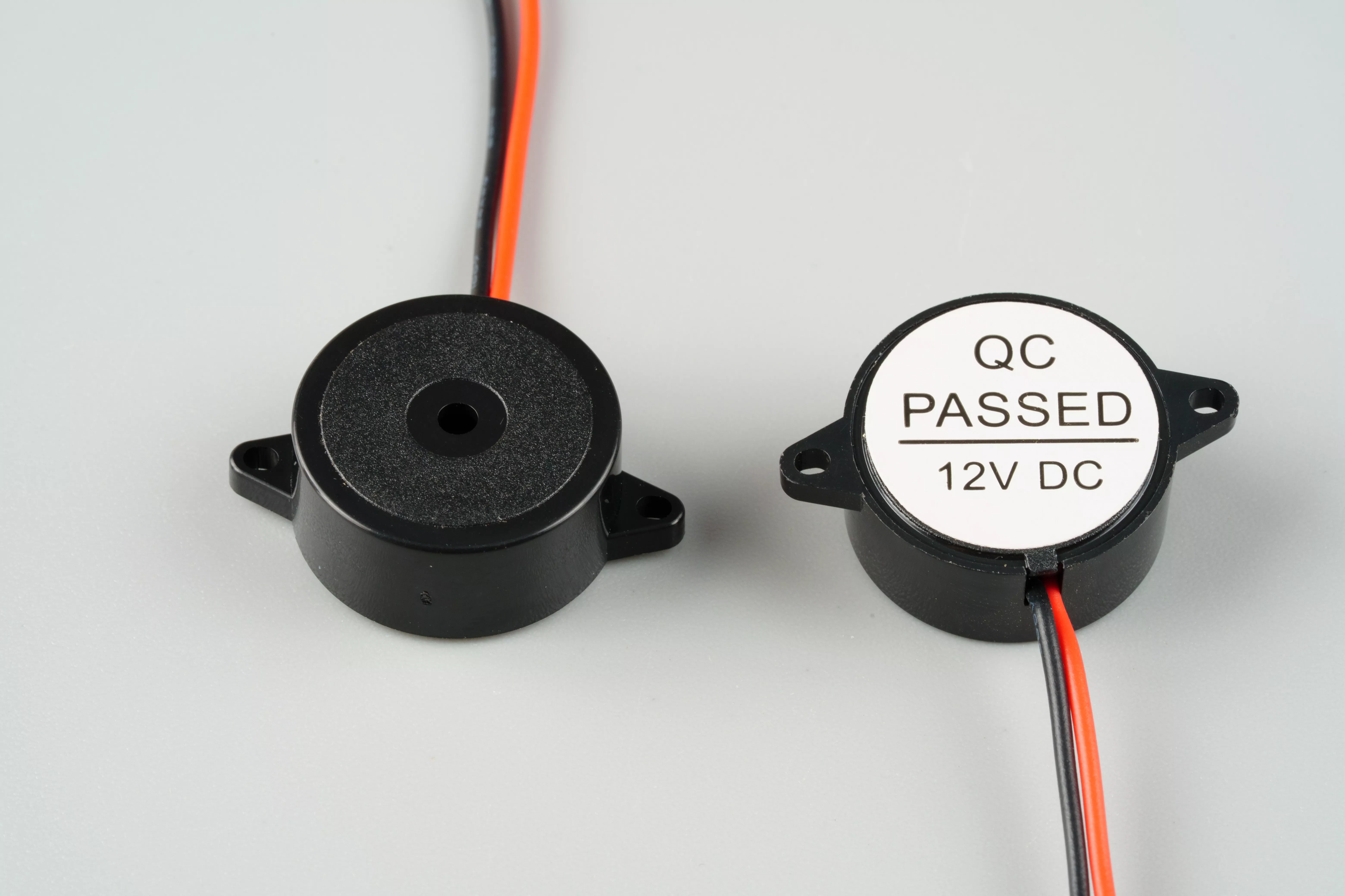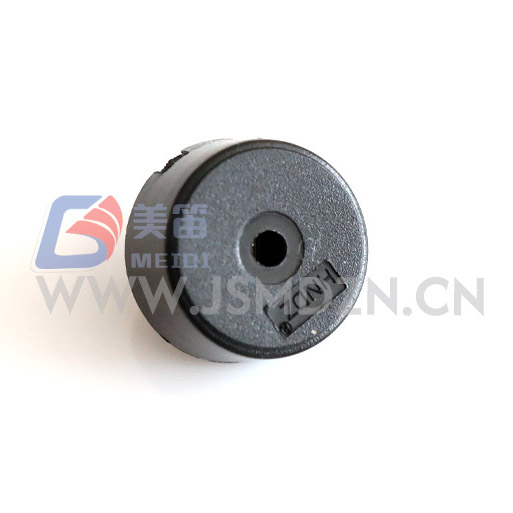
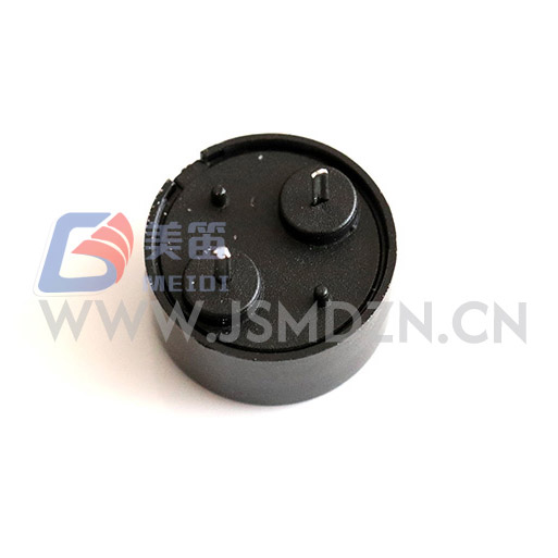
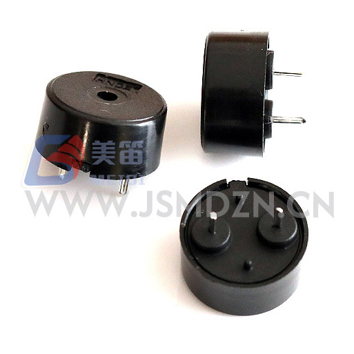
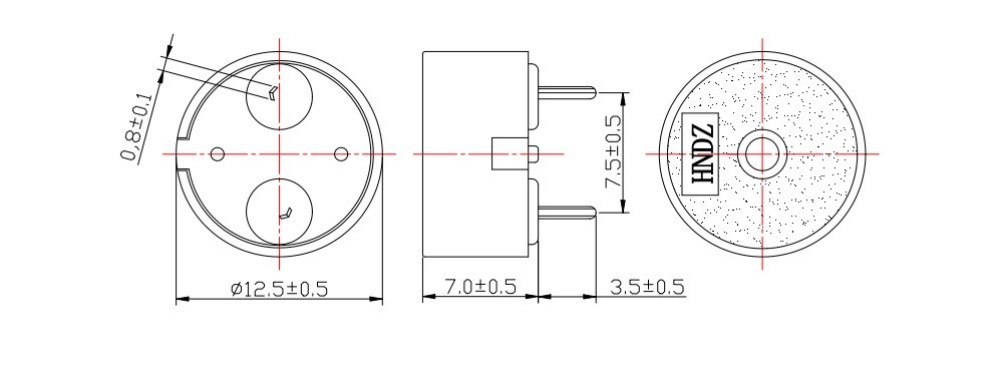
The 1207 Piezoelectric Passive Buzzer with Pogo Pin is a through‑hole passive piezoelectric sounder designed to be driven by an external AC waveform. It measures 12.5 mm in diameter and 7.0 mm in height, with a black PBT housing that weighs approximately 0.66 g. When supplied with a 5 Vp‑p square wave at its 4000 Hz resonant frequency, the buzzer delivers a sound pressure level of at least 80 dB at a distance of 10 cm, while drawing no more than 10 mA. The drive signal can range from 1 V to 30 V peak‑to‑peak, allowing integration with low‑voltage logic as well as higher‑voltage industrial circuits. This passive architecture gives the designer full control over the tone frequency and eliminates the quiescent current draw associated with active oscillator circuits.
| Parameter | Value | Test Conditions |
| Product Type | Piezoelectric Passive Buzzer (Through‑Hole) | — |
| Rated Voltage | 5 Vp‑p | Reference test level |
| Operating Voltage | 1 – 30 Vp‑p | Drive signal range |
| Resonant Frequency | 4000 ± 500 Hz | At rated conditions |
| Sound Output at 10 cm | ≥ 80 dB | 5 Vp‑p, 4000 Hz square wave |
| Current Consumption | ≤ 10 mA | 5 Vp‑p, 4000 Hz square wave |
| Operating Temperature | -20 ℃ ~ +70 ℃ | Continuous |
| Storage Temperature | -30 ℃ ~ +80 ℃ | Non‑operating |
| Dimensions (Dia × H) | 12.5 ± 0.3 × 7.0 ± 0.5 mm | Body only, excluding pins |
| Weight | 0.66 ± 0.2 g | Typical |
| Housing Material | Black PBT | — |
| Wave Soldering ★ | 260 ± 5 ℃, 4–6 s | 2–3 cycles recommended |
| Manual Soldering ★ | 350 ± 10 ℃, 2–5 s | 2–3 cycles recommended |
| Solder Heat Resistance | 250 ± 5 ℃, 10 ± 0.5 s | Body 2.0 mm from solder |
The following measurements were recorded on a 10‑unit sample tested at 5 Vp‑p, 4000 Hz square wave. These values illustrate the typical production distribution and are not guaranteed limits. For the guaranteed performance envelope, refer to the specifications above.
| No. | SPL (dB) | Current (mA) | Capacitance (nF) | Dia (mm) | H (mm) |
| 1 | 84 | 0.45 | 11.7 | 12.01 | 7.1 |
| 2 | 83 | 0.51 | 12.2 | 11.98 | 7.2 |
| 3 | 85 | 0.48 | 12.3 | 12.03 | 6.98 |
| 4 | 84 | 0.45 | 11.9 | 11.99 | 7.0 |
| 5 | 85 | 0.53 | 12.5 | 11.97 | 6.96 |
| 6 | 86 | 0.54 | 11.8 | 11.99 | 6.99 |
| 7 | 85 | 0.49 | 12.3 | 12.02 | 7.3 |
| 8 | 83 | 0.53 | 12.1 | 12.05 | 7.5 |
| 9 | 84 | 0.51 | 11.2 | 12.02 | 7.0 |
| 10 | 83 | 0.49 | 11.9 | 11.98 | 6.98 |
As a passive component, the HNR‑1207 PA7.5 relies on the host system to supply a square wave or PWM signal centered on 4000 Hz. A common implementation uses a microcontroller GPIO pin configured as a timer output, optionally buffered through a transistor when a higher drive voltage than the logic supply is desired. The capacitive nature of the buzzer, with a nominal capacitance around 12 nF, results in short current spikes at each signal edge. Placing a small series resistor (100–330 Ω) in line with the drive pin can limit peak currents without materially affecting sound output. Because the operating voltage spans 1 V to 30 Vp‑p, the same buzzer can be driven directly from a 3.3 V MCU for a moderate alert or boosted to 12 V or 24 V for louder applications.
For volume production assembly, wave soldering at 260 ℃ for 4–6 seconds is the preferred method. Manual soldering with an iron set to 350 ℃ for 2–5 seconds is also acceptable, with up to three thermal cycles permitted. The housing should be kept at least 2.0 mm from the solder bath to avoid deformation.
Every production lot of the 1207 Piezoelectric Passive Buzzer with Pogo Pin is sampled for the seven‑item reliability protocol defined in the product specification. The tests include extended exposure to humidity (50 ℃, 90–95% RH, 48 h), high and low temperature storage, thermal cycling between -30 ℃ and +80 ℃, mechanical drop, vibration, and solder heat resistance. Acceptance requires that all electrical and dimensional specifications are met after a 2‑hour recovery at room temperature.
MEIDI's Jiangsu facility integrates in‑house ceramic processing, automated piezo bonding, and 100% end‑of‑line acoustic verification. The quality management system is certified to ISO 9001, and batch‑specific test data can be supplied with volume shipments.


Equipment that already generates a PWM or square wave output for other purposes can directly use the 1207 Piezoelectric Passive Buzzer with Pogo Pin without adding oscillator circuitry. Battery‑powered portable instruments benefit from the low 10 mA drive current and the absence of a quiescent oscillator load. In industrial control panels operating from 12 V or 24 V DC supplies, the wide voltage acceptance simplifies the driver design. The small 12.5 mm footprint also suits space‑constrained consumer electronics such as smart home sensors and handheld testers.
What drive signal does this buzzer need?
It requires an AC signal, typically a square wave or PWM, at a frequency close to 4000 Hz. Applying a DC voltage will not produce sound and may damage the element.
Can I drive it directly from a microcontroller?
Yes, provided the logic level falls within the 1–30 Vp‑p range. For 3.3 V or 5 V systems, the SPL will be lower than the 80 dB specified at 5 Vp‑p. A transistor buffer can raise the drive voltage when higher output is needed.
What soldering profiles are recommended?
Wave soldering at 260 ℃ for 4–6 seconds is recommended. Manual soldering can be performed at 350 ℃ for 2–5 seconds. Both methods allow up to three thermal cycles.
How should I handle the buzzer after soldering?
The housing is not sealed, so avoid immersion in cleaning solvents or flux. Store the assembled boards in a dry environment to prevent pin oxidation.
For complete datasheets, frequency response curves, or batch‑specific test reports, contact MEIDI with your project requirements. Engineering support typically responds within one business day.
Address
No.6, Wenlin Road, Chenbao Town, Xinghua City, Jiangsu Province, China
Tel