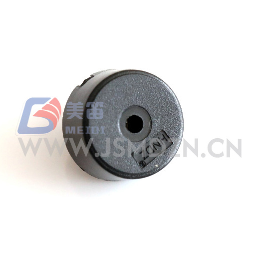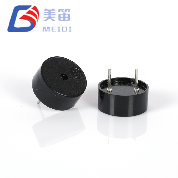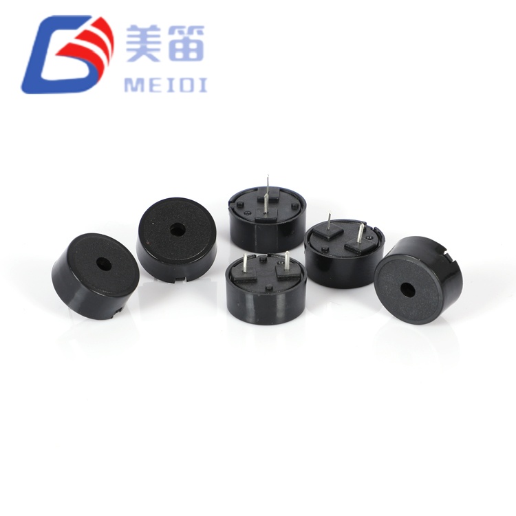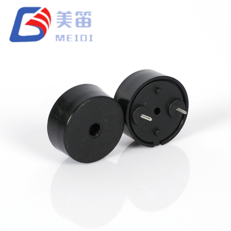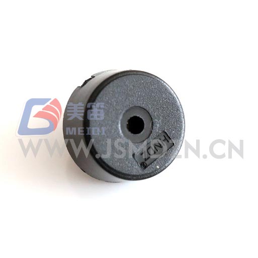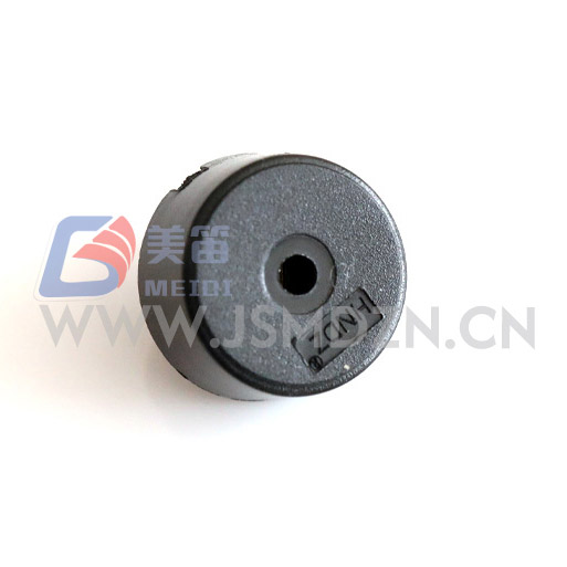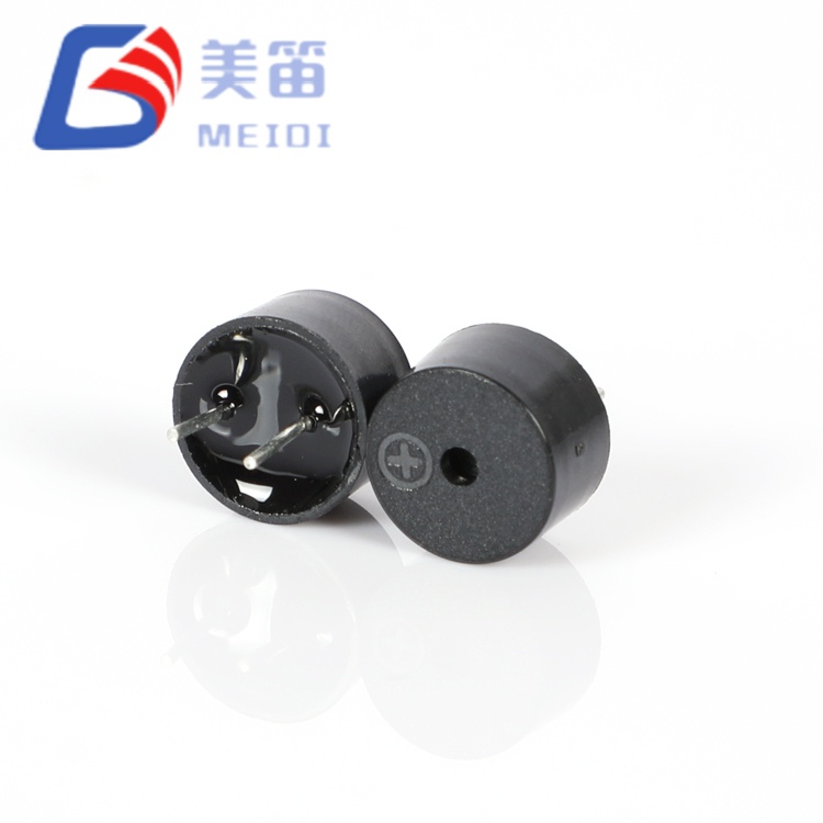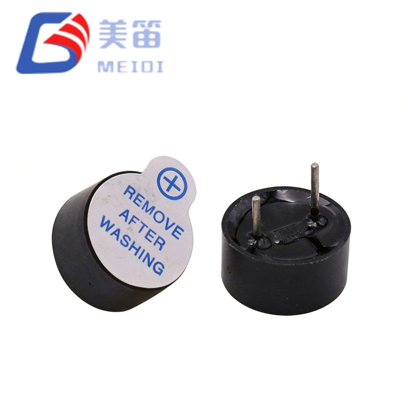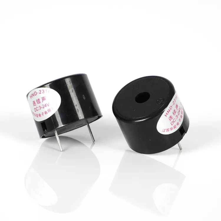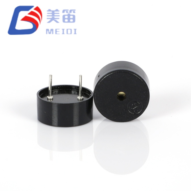
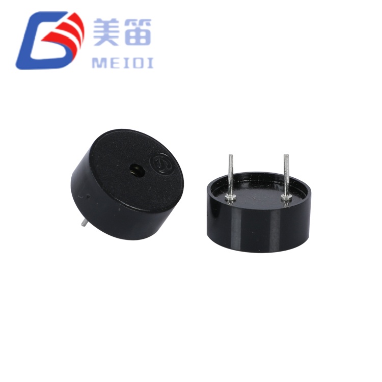
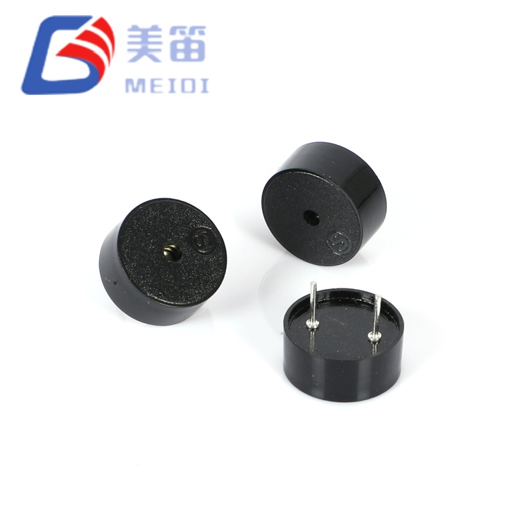
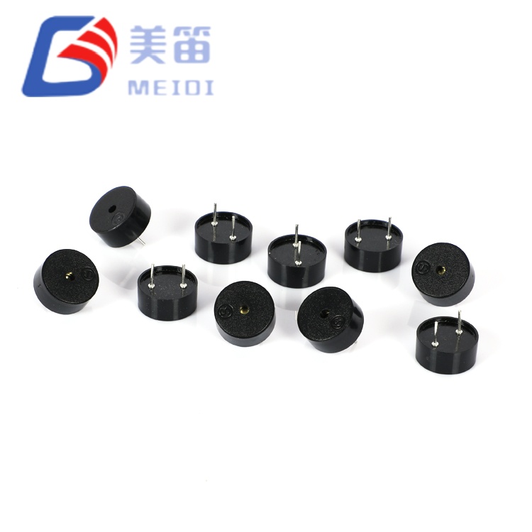
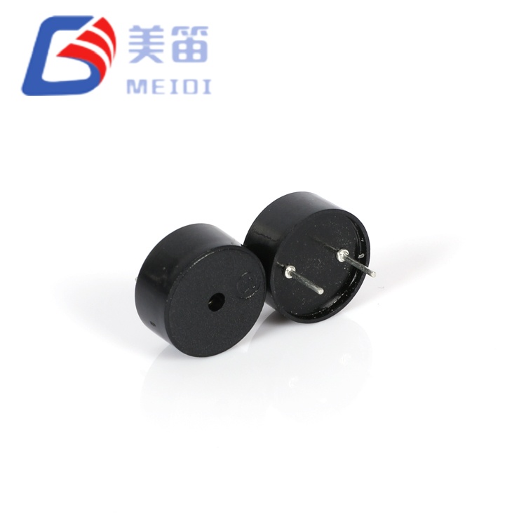
The 1255 Piezoelectric Passive Buzzer with Pogo Pin is a through‑hole passive sounder that relies on an external AC drive signal to produce an audible tone. Measuring 12.5 mm in diameter and 5.5 mm in height, it fits into tight PCB spaces while delivering a minimum sound pressure of 80 dB at 10 cm when driven with a 5 Vp‑p square wave at 4000 Hz. Current consumption remains at or below 10 mA under these conditions, and the drive voltage can span from 1 V to 30 V peak‑to‑peak, allowing direct connection to logic‑level outputs or higher‑voltage industrial buses. The black PBT housing supports both wave and manual soldering and operates across a temperature range of ‑20 ℃ to +70 ℃.
| Parameter | Value | Test Conditions |
| Product Type | Piezoelectric Passive Buzzer (Through‑Hole) | — |
| Rated Voltage | 5 Vp‑p | Reference test condition |
| Operating Voltage | 1 – 30 Vp‑p | Drive signal range |
| Sound Output at 10 cm | ≥ 80 dB | 5 Vp‑p, 4000 Hz square wave |
| Current Consumption | ≤ 10 mA | 5 Vp‑p, 4000 Hz square wave |
| Resonant Frequency | 4000 ± 500 Hz | At rated conditions |
| Operating Temperature | -20 ℃ ~ +70 ℃ | Continuous |
| Storage Temperature | -30 ℃ ~ +80 ℃ | Non‑operating |
| Dimensions (Dia × H) | 12.5 ± 0.3 × 5.5 ± 0.5 mm | Body excluding pins |
| Weight | 0.60 ± 0.2 g | Typical |
| Housing Material | Black PBT | — |
| Wave Soldering ★ | 260 ± 5 ℃, 4–6 s | 2–3 cycles recommended |
| Manual Soldering ★ | 350 ± 10 ℃, 2–5 s | 2–3 cycles recommended |
| Solder Heat Resistance | 250 ± 5 ℃, 10 ± 0.5 s | Body 2.0 mm from solder |
The table below contains measurements from a 10‑unit sample tested at 5 Vp‑p, 4000 Hz square wave. The results illustrate typical production uniformity and are not guaranteed limits. For the specified performance envelope, refer to the technical specifications above.
| No. | SPL (dB) | Current (mA) | Capacitance (nF) | Dia (mm) | H (mm) |
| 1 | 84 | 0.68 | 11.7 | 12.01 | 5.51 |
| 2 | 83 | 0.69 | 12.2 | 11.98 | 5.53 |
| 3 | 85 | 0.72 | 12.3 | 12.03 | 5.54 |
| 4 | 84 | 0.78 | 11.9 | 11.99 | 5.55 |
| 5 | 85 | 0.76 | 12.5 | 11.97 | 5.53 |
| 6 | 86 | 0.72 | 11.8 | 11.99 | 5.51 |
| 7 | 85 | 0.64 | 12.3 | 12.02 | 5.51 |
| 8 | 83 | 0.69 | 12.1 | 12.05 | 5.53 |
| 9 | 84 | 0.73 | 14.2 | 12.02 | 5.51 |
| 10 | 83 | 0.63 | 11.9 | 11.98 | 5.54 |
Capacitance values originate from the test report header and are not part of the core specification. Contact MEIDI for production batch‑specific data.
Because the 1255 Piezoelectric Passive Buzzer with Pogo Pin is a passive buzzer, it depends on the host system to provide a square wave or PWM signal centered at 4000 Hz. A microcontroller timer output can serve as a direct source, although the sound pressure will be lower at 3.3 V or 5 V logic levels than at the full 30 Vp‑p capability. Adding a simple transistor buffer or logic gate driver between the MCU pin and the buzzer allows the drive amplitude to be increased independently of the microcontroller supply. The capacitive load, typically around 12 nF, causes brief current peaks at each signal edge. A small series resistor (100 Ω to 330 Ω) helps to limit these peaks while preserving acoustic output.
Both wave and manual soldering are supported. Wave soldering is performed at 260 ℃ for 4–6 seconds, and hand soldering at 350 ℃ for 2–5 seconds. Up to three thermal cycles are permitted, and the housing must remain at least 2.0 mm from the solder bath or iron tip.
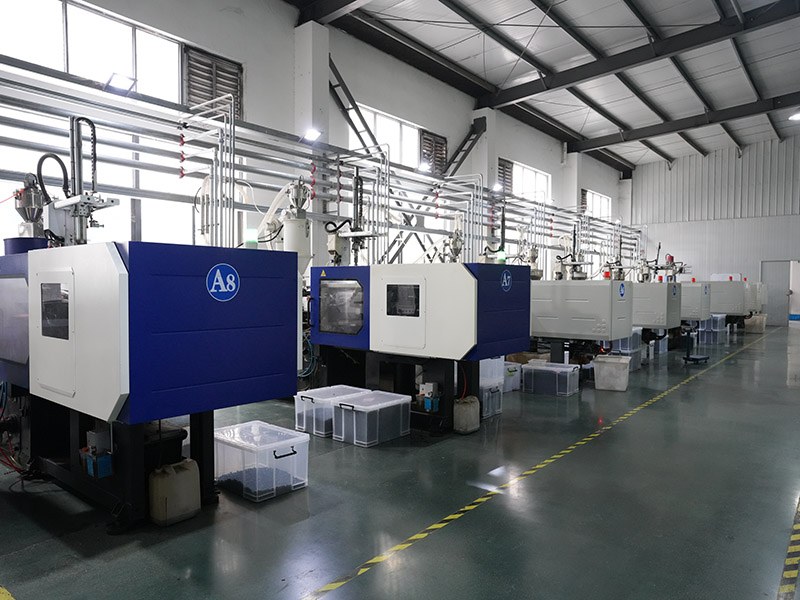
MEIDI applies a seven‑item reliability protocol to each production lot of the HNR‑1255 PA6.5, consistent with the product specification. The testing sequence includes extended humidity exposure, high and low temperature storage, thermal cycling, mechanical drop, vibration, and solder heat resistance. After each stress, parts are allowed to recover at room temperature for two hours before electrical and dimensional verification. All tests are conducted within the framework of the company's ISO 9001 certified quality system, and batch‑level reports can be provided with volume shipments.

The passive architecture of this buzzer is a good fit for designs that already generate a PWM or square wave output. Portable equipment operating from batteries can benefit from the modest 10 mA drive current and the absence of a quiescent oscillator load. Industrial panels with 12 V or 24 V DC supplies can drive the buzzer directly within its wide voltage tolerance. Consumer electronics such as smart home sensors and handheld diagnostic tools also appreciate the 12.5 mm footprint. For applications that require specific safety or medical certifications, please consult MEIDI to confirm the current compliance status.
What drive signal does the HNR‑1255 PA6.5 need?
An AC signal is required, typically a square wave or PWM at approximately 4000 Hz. Applying a steady DC voltage will not generate sound and may damage the piezoelectric element.
Can it be driven directly by a microcontroller?
Yes, provided the peak‑to‑peak voltage of the pin falls within the 1–30 V range. At 3.3 V or 5 V logic, the sound level will be below the rated 80 dB. A transistor buffer can be used to reach higher drive voltages when louder output is required.
What soldering methods are recommended?
Both wave soldering (260 ℃, 4–6 s) and manual soldering (350 ℃, 2–5 s) are acceptable, with a maximum of three thermal cycles. Maintain a minimum distance of 2.0 mm between the housing and the heat source.
For complete datasheets, frequency response curves, or batch‑specific test data, please contact MEIDI with your application details. Engineering support typically responds within one business day.
Address
No.6, Wenlin Road, Chenbao Town, Xinghua City, Jiangsu Province, China
Tel