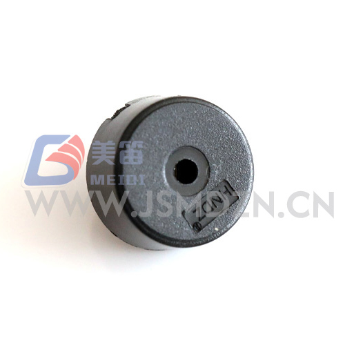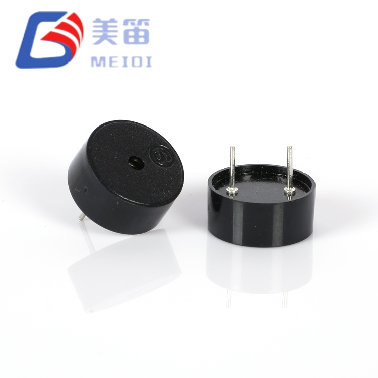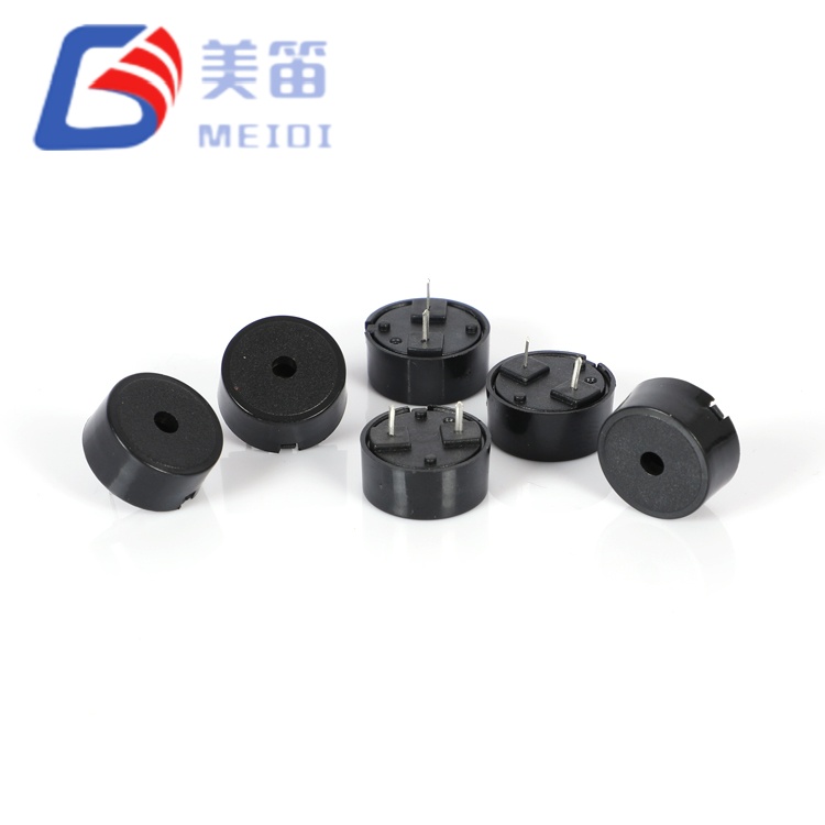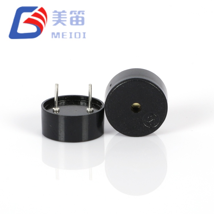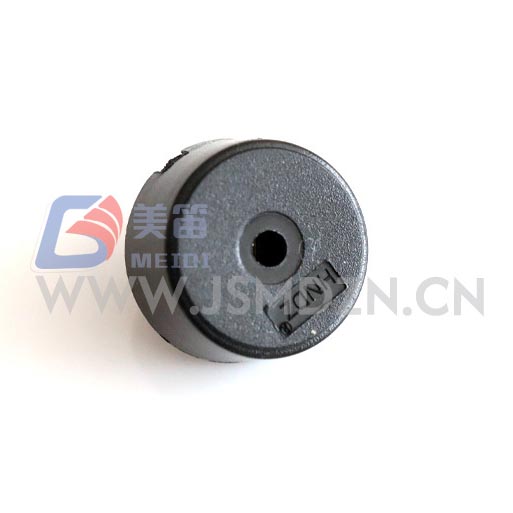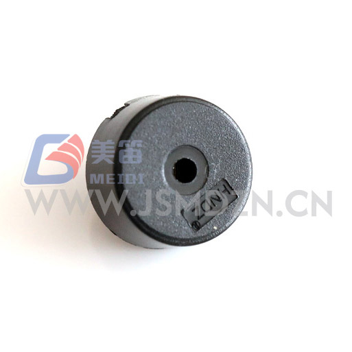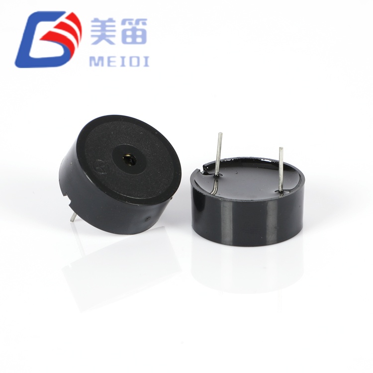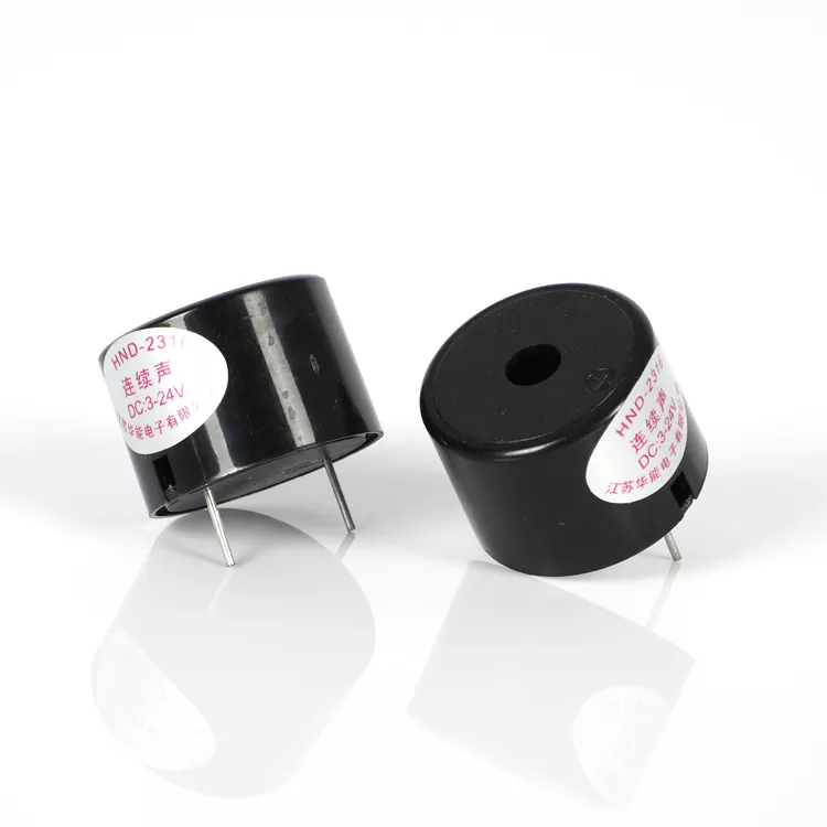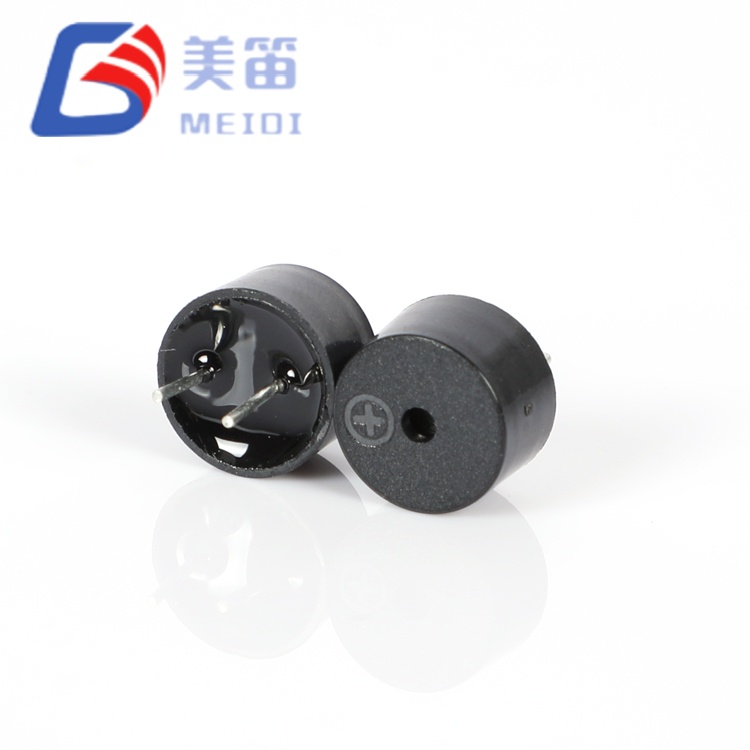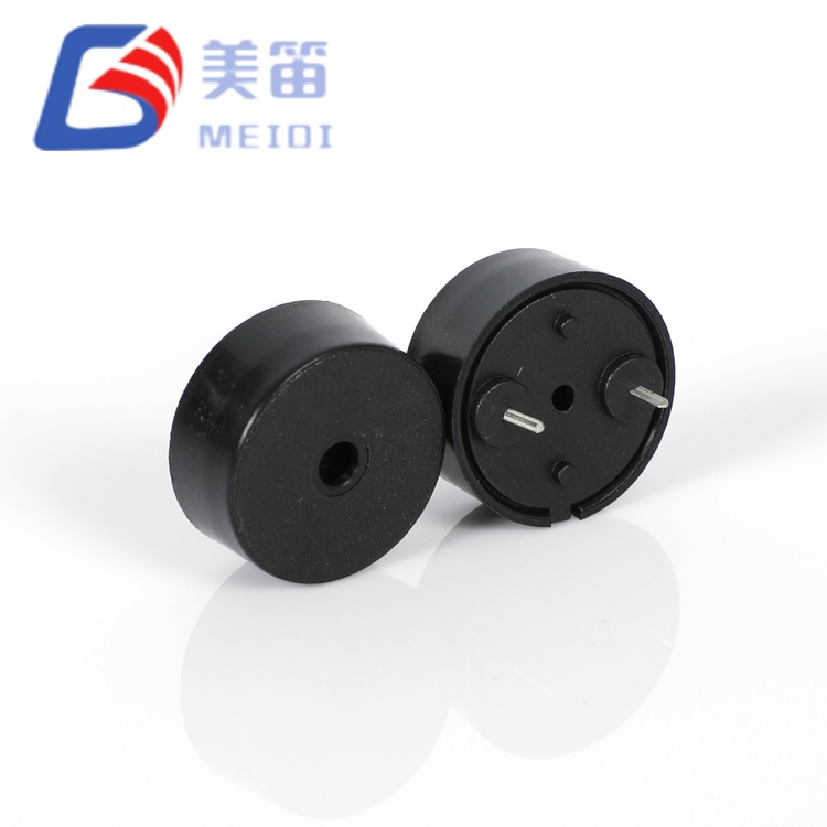
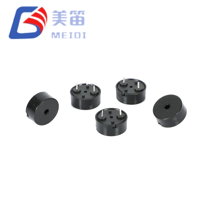
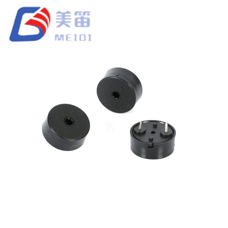
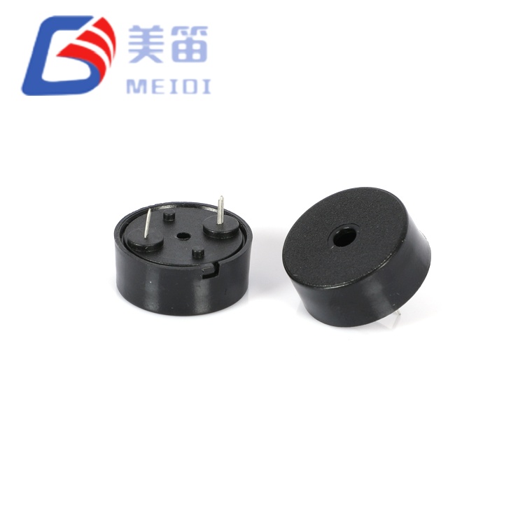
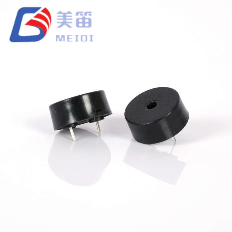
The 1707 Piezoelectric Passive Buzzer with Pogo Pin is a through‑hole passive sounder built to accept an external AC drive signal for tone generation. It occupies a 17 mm diameter footprint with a height of 7.5 mm, making it suitable for PCB layouts where space is moderately constrained. With a rated drive level of 5 Vp‑p at 4000 Hz, it delivers a sound pressure of at least 85 dB at 10 cm while keeping current draw at or below 10 mA. The operating voltage range extends from 1 V to 30 V peak‑to‑peak, so designers can connect the buzzer directly to a microcontroller pin or boost the signal for higher acoustic output. The black PBT housing is compatible with wave and manual soldering profiles and remains mechanically stable across an operating temperature span of ‑20 ℃ to +70 ℃.
| Parameter | Value | Test Conditions |
| Product Type | Piezoelectric Passive Buzzer (Through‑Hole) | — |
| Rated Voltage | 5 Vp‑p | Reference test condition |
| Operating Voltage | 1 – 30 Vp‑p | Drive signal range |
| Sound Output at 10 cm | ≥ 85 dB | 5 Vp‑p, 4000 Hz square wave |
| Current Consumption | ≤ 10 mA | 5 Vp‑p, 4000 Hz square wave |
| Resonant Frequency | 4000 Hz | At rated conditions |
| Operating Temperature | -20 ℃ ~ +70 ℃ | Continuous |
| Storage Temperature | -30 ℃ ~ +80 ℃ | Non‑operating |
| Dimensions (Dia × H) | 17.0 ± 0.3 × 7.5 ± 0.5 mm | Body excluding pins |
| Weight | 1.35 g | Typical |
| Housing Material | Black PBT | — |
| Wave Soldering ★ | 260 ± 5 ℃, 4–6 s | 2–3 cycles recommended |
| Manual Soldering ★ | 350 ± 10 ℃, 2–5 s | 2–3 cycles recommended |
| Solder Heat Resistance | 250 ± 5 ℃, 10 ± 0.5 s | Body 2.0 mm from solder |
The data below comes from a 10‑unit sample driven at 5 Vp‑p, 4000 Hz square wave. It reflects the typical spread observed in production. The guaranteed limits are defined in the technical specifications above, not by this sample set.
| No. | SPL (dB) | Current (mA) | Capacitance (nF) | Dia (mm) | H (mm) |
| 1 | 94 | 0.83 | 16.2 | 17.01 | 7.51 |
| 2 | 92 | 0.93 | 12.2 | 16.98 | 7.53 |
| 3 | 92 | 1.00 | 12.7 | 17.10 | 7.49 |
| 4 | 93 | 0.81 | 11.9 | 17.06 | 7.49 |
| 5 | 94 | 0.98 | 12.5 | 16.92 | 7.48 |
| 6 | 91 | 0.93 | 12.7 | 17.01 | 7.51 |
| 7 | 93 | 0.81 | 12.3 | 17.02 | 7.53 |
| 8 | 91 | 0.89 | 12.1 | 16.99 | 7.51 |
| 9 | 94 | 0.93 | 14.2 | 16.98 | 7.47 |
| 10 | 94 | 0.84 | 12.9 | 17.01 | 7.52 |
Capacitance values are taken from test report headers for reference and are not part of the guaranteed specification. Contact MEIDI for batch‑specific test documentation.
This 1707 Piezoelectric Passive Buzzer with Pogo Pin requires an external square wave or PWM signal centered at 4000 Hz. A common approach is to use a microcontroller timer output, though the sound pressure at 3.3 V or 5 V logic levels will be lower than the rated 85 dB. To reach higher volumes, a transistor buffer or logic gate can raise the drive amplitude up to the 30 Vp‑p maximum. The capacitive load of the buzzer, roughly 12 nF in typical builds, produces transient current spikes at each signal edge. Inserting a small series resistor in the 100 Ω to 330 Ω range helps manage these peaks without a significant drop in loudness.
For production, wave soldering at 260 ℃ for 4–6 seconds is recommended. Manual soldering at 350 ℃ for 2–5 seconds is also supported, with up to three thermal cycles allowed. Maintain a clearance of at least 2.0 mm between the housing and the solder source.
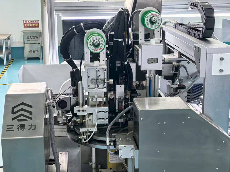
MEIDI has been focused on acoustic component production since 2011. The company operates a facility in Jiangsu Province with over 500 employees and a monthly output exceeding 50 million buzzer units. In‑house processes cover ceramic powder preparation, electrode printing, polarization, injection molding, and automated assembly, which together provide tight control over material quality and production lead times. Every HNR‑1707 PA10 passes an end‑of‑line acoustic check, and each lot is sampled for the reliability sequence defined in the product specification. This integrated manufacturing model, certified to ISO 9001, supports consistent batch performance for both trial quantities and high‑volume orders.


Equipment that already generates a square wave or PWM output can integrate this buzzer without adding an extra oscillator circuit. Battery‑operated devices benefit from the modest 10 mA consumption and the absence of standby current. Industrial panels running on 12 V or 24 V DC buses can drive the buzzer directly within its 1–30 Vp‑p range. Consumer products such as smart home sensors, portable medical tools, and handheld test instruments also fit the 17 mm footprint. If the intended use involves safety‑related or regulated environments, please contact MEIDI to verify the applicable certifications.
What drive signal does the HNR‑1707 PA10 need?
It must be driven by an AC waveform, usually a square wave or PWM at around 4000 Hz. A DC voltage alone will not produce sound and may harm the element.
Can I drive it directly from a microcontroller pin?
Yes, as long as the pin’s peak‑to‑peak voltage lies within the 1–30 V range. At 3.3 V or 5 V logic, the sound output will be lower than the rated 85 dB. A transistor buffer can increase the drive level when louder alerts are required.
What soldering profiles are recommended?
Wave soldering at 260 ℃ for 4–6 seconds is preferred for volume assembly. Manual soldering at 350 ℃ for 2–5 seconds is also acceptable, with a limit of three thermal cycles. Always keep the housing at least 2.0 mm from the solder bath or iron tip.
Does the resonant frequency have a tolerance?
The specification states a center frequency of 4000 Hz without a stated tolerance. For frequency‑sensitive designs, MEIDI can provide additional characterization data to help define the expected range in production.
For complete datasheets, frequency response curves, or batch‑specific quality records, please contact MEIDI with your project details. Engineering support normally responds within one business day.
Address
No.6, Wenlin Road, Chenbao Town, Xinghua City, Jiangsu Province, China
Tel