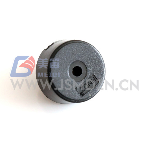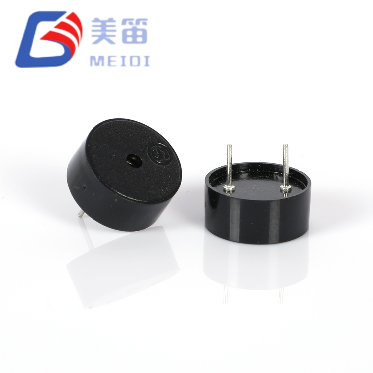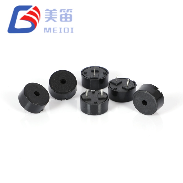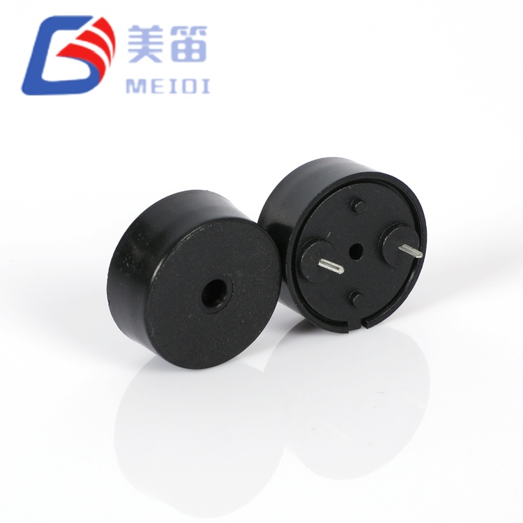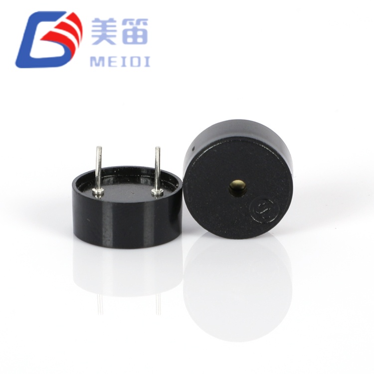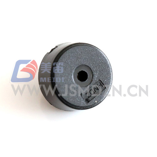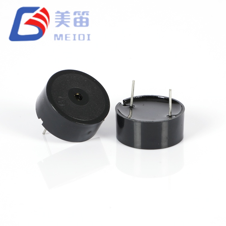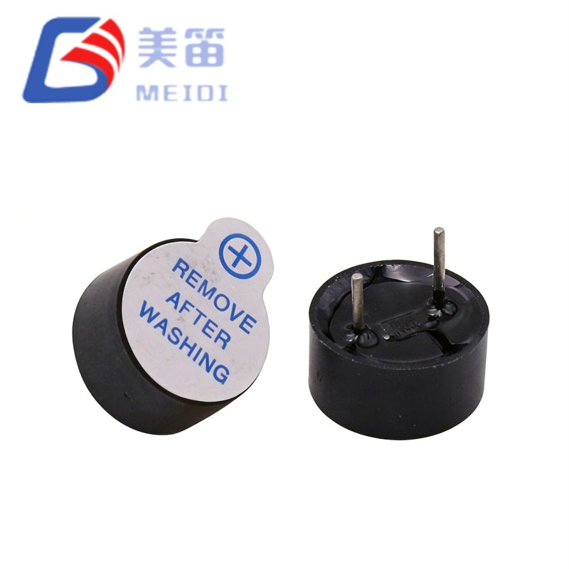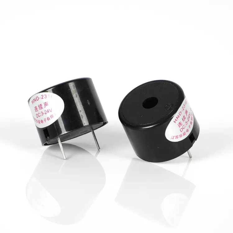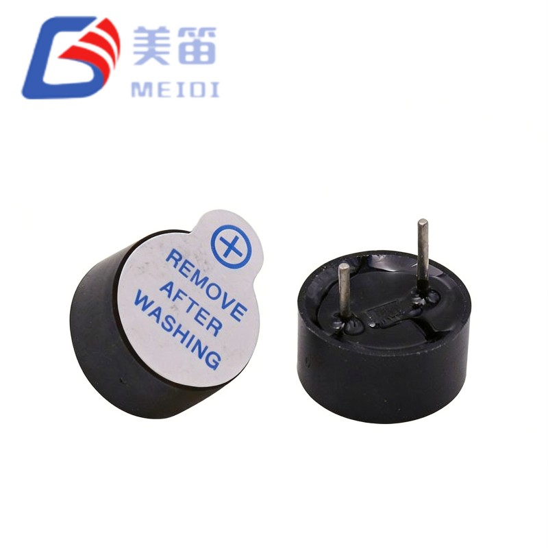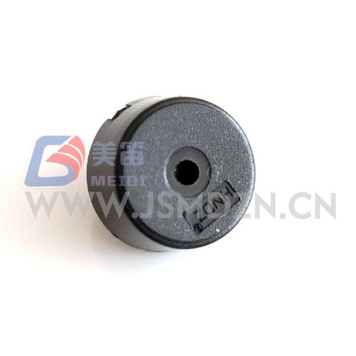
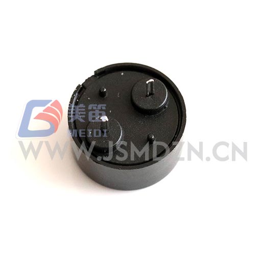
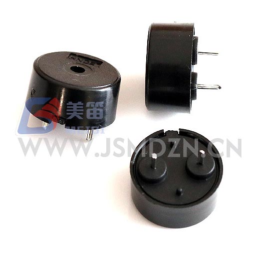
The 1404 Piezoelectric Passive Buzzer with Pogo Pin is a compact through‑hole passive buzzer that relies on an external AC drive signal to generate sound. With a diameter of 13.8 mm and a low profile of only 4.0 mm, it fits into space‑constrained PCB layouts. A 5 Vp‑p square wave at 4000 Hz produces a sound pressure level of at least 80 dB at 10 cm while drawing no more than 10 mA. The drive circuit can accept signals from 1 V to 30 V peak‑to‑peak, giving designers flexibility to use logic‑level outputs directly or boost the voltage for higher volume. Its black PBT housing withstands manual soldering temperatures and operates reliably from -20 ℃ to +70 ℃.
| Parameter | Value | Test Conditions |
| Product Type | Piezoelectric Passive Buzzer (Through‑Hole) | — |
| Rated Voltage | 5 Vp‑p | Reference test condition |
| Operating Voltage | 1 – 30 Vp‑p | Drive signal range |
| Sound Output at 10 cm | ≥ 80 dB | 5 Vp‑p, 4000 Hz square wave |
| Current Consumption | ≤ 10 mA | 5 Vp‑p, 4000 Hz square wave |
| Resonant Frequency | 4000 Hz | No tolerance stated in specification |
| Operating Temperature | -20 ℃ ~ +70 ℃ | Continuous |
| Storage Temperature | -30 ℃ ~ +80 ℃ | Non‑operating |
| Dimensions (Dia × H) | 13.8 ± 0.4 × 4.0 ± 0.5 mm | Body excluding pins |
| Weight | 0.67 ± 0.1 g | Typical |
| Housing Material | Black PBT | — |
| Manual Soldering ★ | 350 ± 10 ℃, 2–5 s | 2–3 cycles recommended |
| Solder Heat Resistance | 250 ± 5 ℃, 10 ± 0.5 s | Body 2.0 mm from solder |
| No. | SPL (dB) | Current (mA) | Capacitance (nF) | Dia (mm) | H (mm) |
| 1 | 85 | 0.73 | 11.5 | 14.01 | 4.10 |
| 2 | 84 | 0.82 | 12.0 | 13.90 | 4.05 |
| 3 | 83 | 0.74 | 12.1 | 14.00 | 4.00 |
| 4 | 85 | 0.76 | 11.2 | 13.98 | 4.01 |
| 5 | 84 | 0.78 | 12.5 | 13.92 | 3.98 |
| 6 | 85 | 0.72 | 12.1 | 14.02 | 4.02 |
| 7 | 83 | 0.80 | 12.3 | 13.89 | 4.02 |
| 8 | 84 | 0.79 | 12.1 | 14.03 | 3.99 |
| 9 | 85 | 0.80 | 12.4 | 13.95 | 4.01 |
| 10 | 86 | 0.76 | 12.9 | 13.98 | 4.02 |
These sample results show a typical production distribution. The guaranteed performance boundaries are defined in the specifications above. Capacitance values appear in the test report header and are not part of the main parameter table. Contact MEIDI for batch‑specific test data.
Since this buzzer is a passive component, it requires an external AC waveform for operation. A microcontroller GPIO configured as a PWM output at 4000 Hz is a common solution. When the logic voltage is 3.3 V or 5 V, the sound output will be lower than the rated 80 dB; a simple transistor buffer can raise the drive level up to the desired voltage within the 1–30 Vp‑p window. The capacitive nature of the buzzer, typically around 12 nF, causes brief current spikes during signal transitions. A small series resistor in the range of 100–330 Ω helps limit peak currents without noticeably reducing loudness.
For production assembly, manual soldering is recommended at 350 ℃ for 2–5 seconds per joint, with a maximum of three thermal cycles. Keep the housing at least 2.0 mm away from the solder iron to prevent deformation.
The 1404 Piezoelectric Passive Buzzer with Pogo Pin is manufactured under MEIDI's ISO 9001 quality system. Every production lot undergoes a set of reliability tests defined in the product specification. These tests include:
Humidity exposure at 50 ℃ and 90–95% RH for 48 hours, followed by a 2‑hour room‑temperature recovery before measurement.
High temperature storage at +80 ℃ for 48 hours and low temperature storage at -30 ℃ for 48 hours, each with a 2‑hour recovery period.
Temperature cycling from -30 ℃ to +80 ℃ with 30‑minute dwells, repeated for five cycles, then recovered for 2 hours.
A drop test from 75 cm onto a hardwood board (three drops) and a vibration test sweeping from 10 Hz to 55 Hz at 1.0 mm amplitude for 0.5 hours overall.
Solder heat resistance test with leads immersed in molten solder at 250 ℃ for 10 seconds, maintaining 2.0 mm clearance from the housing.
After each test, all electrical and dimensional parameters must meet the original specification. Contact MEIDI for detailed test reports from specific production batches.


The passive design of the HNR‑1404 PA7.5 is well suited to equipment that already generates a PWM or square wave signal. Battery‑operated instruments benefit from the low drive current and the absence of a quiescent oscillator load. Industrial panels that run on 12 V or 24 V DC rails can directly drive the buzzer within its wide voltage tolerance. Consumer electronics such as smart home sensors or handheld testers also appreciate the small footprint and through‑hole mounting. For any application that may require specific safety or regulatory certifications, please verify with MEIDI before finalizing the design.
What kind of drive signal does this buzzer need?
It requires an AC signal, typically a square wave or PWM at approximately 4000 Hz. A steady DC voltage will not produce sound and could damage the piezoelectric element.
Can I drive it directly from a microcontroller pin?
Yes, if the pin's output voltage falls within the 1–30 Vp‑p range. At 3.3 V or 5 V logic levels, the sound output will be below the rated 80 dB. A transistor buffer can be added to increase the drive voltage and loudness.
What soldering method is recommended?
Manual soldering with an iron set to 350 ℃ is the standard method. Each joint should be heated for 2–5 seconds, and up to three rework cycles are acceptable. Avoid letting the housing touch the solder directly.
For complete datasheets, frequency response plots, or batch‑specific test reports, please contact MEIDI with your project requirements. Engineering support typically responds within one business day.
Address
No.6, Wenlin Road, Chenbao Town, Xinghua City, Jiangsu Province, China
Tel