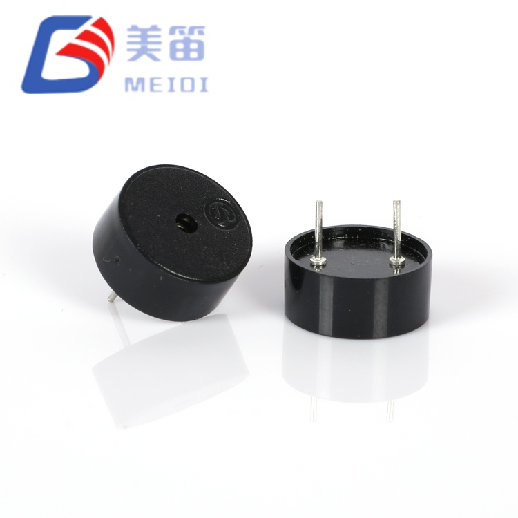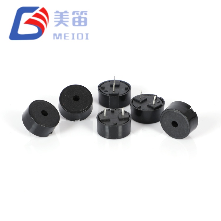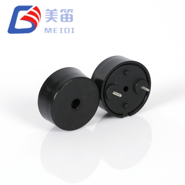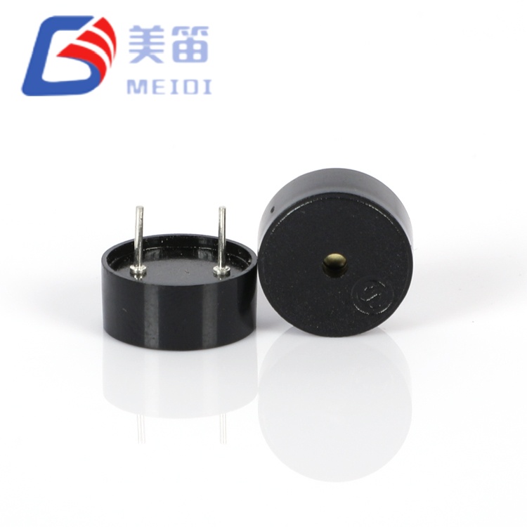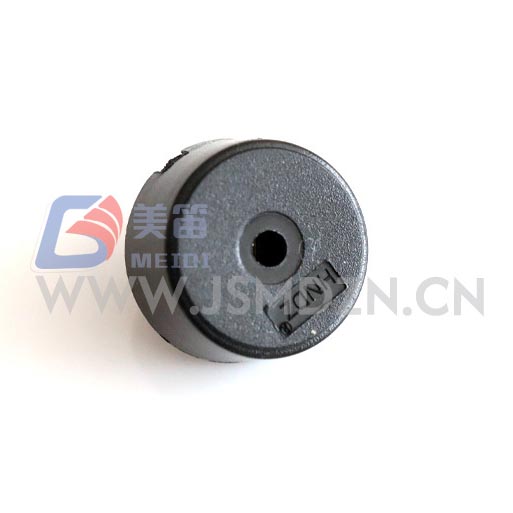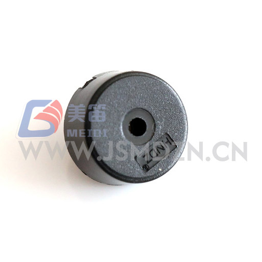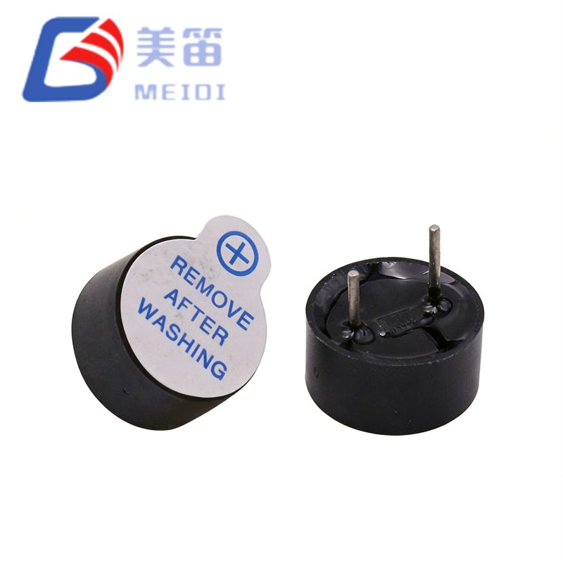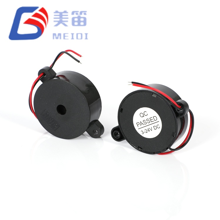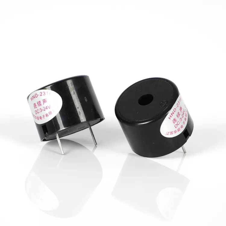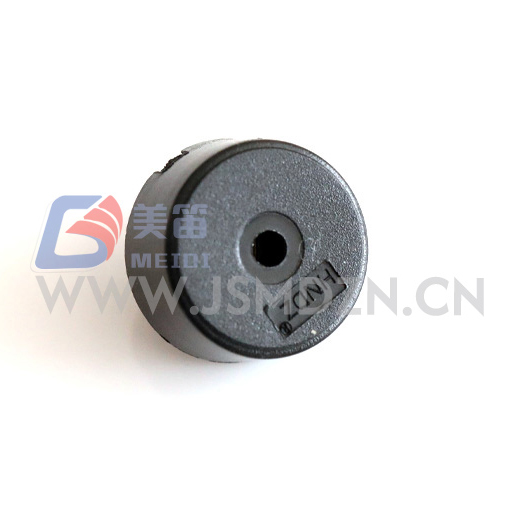
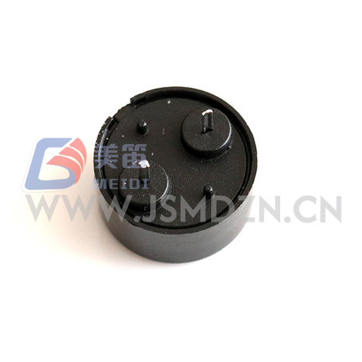
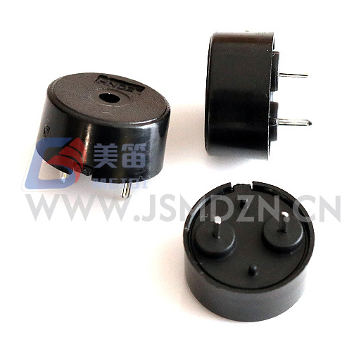
The HNR‑1207 PA6.5 Piezoelectric Passive Buzzer with Spring-Loaded Pogo Pins is a through‑hole piezoelectric passive buzzer engineered for battery‑operated and energy‑harvesting systems where every microampere affects runtime. Consuming a measured 0.45–0.54 mA at 5 Vp‑p (4000 Hz), this component delivers ≥80 dB SPL with less than one‑tenth the current of typical electromagnetic active buzzers, significantly extending battery life in portable medical devices, wearable monitors, and wireless sensor nodes.
Manufactured at MEIDI’s Jiangsu facility, the HNR‑1207 PA6.5 features a 12.5 mm piezoelectric ceramic diaphragm in a 7.0 mm‑tall housing, weighing only 0.66 g. Its capacitive load (10 nF nominal) enables direct drive from most microcontroller GPIO pins without external transistors, while the 1–30 V operating range consolidates multiple voltage‑specific SKUs into a single component for 3.3 V, 5 V, 12 V, and 24 V systems. The black PBT housing withstands wave soldering at 260 °C and manual rework at 350 °C, supporting both automated assembly and field repair.
The HNR‑1207 PA6.5 is a passive piezoelectric buzzer requiring external AC excitation — typically a 4000 Hz square wave from a microcontroller PWM pin, timer output, or dedicated driver IC. Unlike electromagnetic buzzers that drive a current‑hungry coil, this device uses a piezoelectric ceramic element that flexes under applied voltage, presenting a primarily capacitive load. This fundamental difference results in current consumption that is orders of magnitude lower: measured 0.45–0.54 mA at 5 Vp‑p, compared to 20–30 mA for electromagnetic active alternatives.
The ultra‑wide 1–30 V operating range is exceptionally broad for a piezo passive buzzer. At 3.3 V, the device produces audible output suitable for proximity alerts and status tones. At 5 V, it meets the ≥80 dB specification. At 12 V or 24 V, SPL increases further while current remains low — the capacitive nature means power consumption scales with switching frequency rather than voltage amplitude. This voltage elasticity enables procurement consolidation: a single part number serves 3.3 V IoT nodes, 5 V consumer devices, 12 V automotive modules, and 24 V industrial controllers without voltage regulation circuitry.
The 4000 ± 500 Hz resonant frequency sits at the upper edge of the human auditory sensitivity peak (2–4 kHz), producing a crisp, attention‑demanding tone that cuts through ambient noise with minimal power. The through‑hole mounting with polarized pins ensures correct polarity and mechanical retention in vibration‑prone environments. The 0.66 g mass minimises inertial loading on PCB assemblies, an important consideration for wearable and handheld devices where mass budgets are tight.
Sub‑milliampere current draw – measured 0.45–0.54 mA at rated conditions; significantly lower consumption than electromagnetic alternatives
1–30 V ultra‑wide operating range – single SKU serves 3.3 V, 5 V, 12 V, and 24 V systems without voltage conversion
10 nF capacitive load – direct MCU GPIO drive in most applications; no external transistor or driver IC required
4000 Hz crisp tonal output – human‑auditory sweet‑spot frequency with low harmonic distortion from piezoelectric actuation
0.66 g ultra‑light mass – minimal inertial loading for wearable, handheld, and vibration‑sensitive PCB assemblies
Through‑hole polarized mounting – mechanical retention and polarity protection in industrial and automotive installations
| Parameter | Value | Test Conditions |
| Product Type | Piezoelectric Passive Buzzer | — |
| Rated Voltage | 5 V (Vp‑p) | Square wave, 4000 Hz |
| Operating Voltage | 1 – 30 V (Vp‑p) | Continuous |
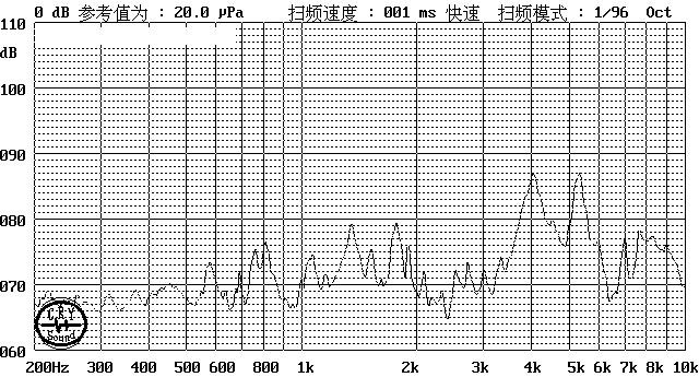
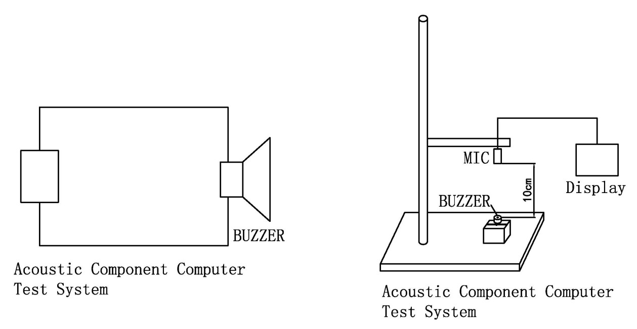
| Sound Output | ≥ 80 dB | At 5 Vp‑p, 4000 Hz, 10 cm |
| Resonant Frequency | 4000 ± 500 Hz | At rated voltage |
| Current Consumption | ≤ 10 mA | At 5 Vp‑p, 4000 Hz; measured 0.45–0.54 mA |
| Capacitance | 10 ± 40% nF | At 1 kHz, 25 ℃ |
| Operating Temperature | -20 ℃ ~ +70 ℃ | Continuous |
| Storage Temperature | -30 ℃ ~ +80 ℃ | Non‑operating |
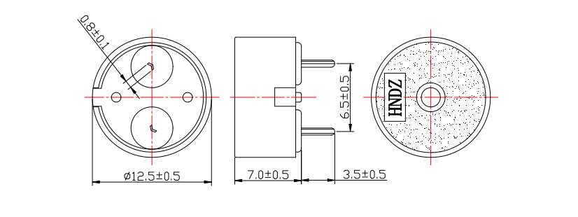
| Dimensions (Dia × H) | 12.5 × 7.0 mm | Body only |
| Weight | 0.66 ± 0.2 g | Typical |
| Housing Material | Black PBT | UL94 V‑0 |
| Mounting Type | Through‑hole | Polarised pins |
| Soldering Temperature (Wave) | 260 ± 5 ℃ | 4–6 s, recommended |
| Soldering Temperature (Manual) | 350 ± 10 ℃ | 2–5 s, recommended |
Wearable health monitors – medication reminders, fall‑detection alerts, and glucose threshold alarms where battery life is the primary design constraint
Portable medical devices – pulse oximeter limit tones, nebuliser cycle completion beeps, and digital thermometer fever alerts in battery‑operated instruments
IoT sensor nodes – environmental threshold warnings, connectivity status chirps, and tamper‑detection alerts in solar‑powered or coin‑cell wireless sensors
Smart metering systems – usage‑limit notifications, communication‑failure warnings, and tamper alerts in battery‑backed utility meters
Automotive 12 V/24 V interior modules – seatbelt reminders, key‑in‑ignition chimes, and diagnostic tool feedback without voltage regulator overhead
Industrial 24 V control panels – fault indication, cycle‑completion tones, and limit‑switch alerts in PLC and relay‑logic systems
| Design Challenge | HNR‑1207 PA6.5 Solution |
| Battery runtime is primary constraint | 0.45–0.54 mA draw extends coin‑cell life significantly vs. electromagnetic alternatives |
| Multi‑voltage product family | Single 1–30 V SKU replaces 3.3 V, 5 V, 12 V, and 24 V specific buzzers; reduces BOM lines and inventory |
| No spare MCU pins for dedicated driver | 10 nF load drives directly from GPIO; no transistor, resistor, or inductor required |
| Wearable weight budget <1 g | 0.66 g mass meets strict wearable constraints without acoustic compromise |
| EMC‑sensitive medical/RF environment | Piezoelectric actuation generates no magnetic field; zero risk of ECG/EEG interference |
The Piezoelectric Passive Buzzer with Spring-Loaded Pogo Pins occupies a distinct efficiency tier in MEIDI’s acoustic portfolio. Where electromagnetic buzzers prioritise plug‑and‑play simplicity, this 1–30 V piezo passive buzzer trades the integrated oscillator for orders‑of‑magnitude current reduction and voltage flexibility. For battery‑powered, multi‑voltage, or mass‑constrained designs, the efficiency gain justifies the external drive requirement.
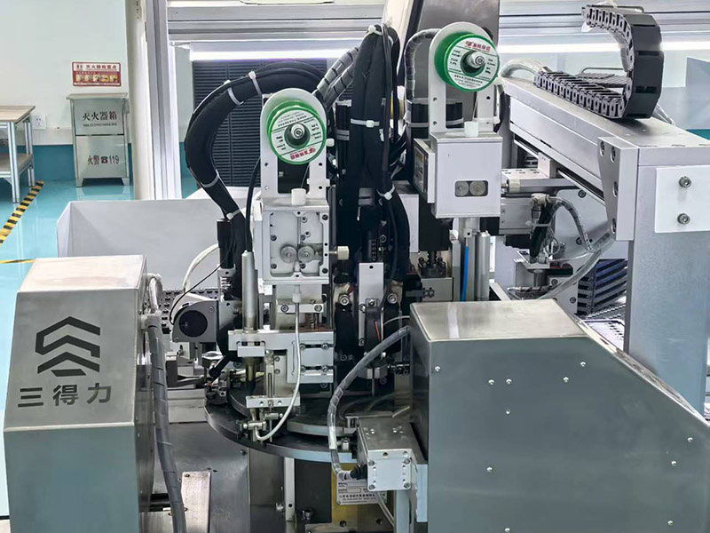
MEIDI manufactures the HNR‑1207 PA6.5 on dedicated piezoelectric assembly lines with automated ceramic bonding, electrode termination, and frequency tuning stations. Our Jiangsu manufacturing base follows ISO 9001 quality management protocols, with statistical process control at each production stage.


Each production lot undergoes comprehensive verification:
Capacitance 100% test – 10 nF ±40% verification at 1 kHz for drive circuit matching; measured range 11.2–12.5 nF in production samples
Resonant frequency sampling – 4000 Hz ±12.5% statistical verification; typical measured range 3900–4080 Hz
SPL batch verification – ≥80 dB minimum at 5 Vp‑p, 4000 Hz; measured sample range 83–86 dB
Current consumption validation – ≤10 mA maximum; measured 0.45–0.54 mA confirms sub‑milliampere performance
High‑temperature storage – 48 hours at +80 ± 2 ℃ (storage test, not operating); parameter recovery after 2‑hour ambient stabilisation
Low‑temperature storage – 48 hours at -30 ± 2 ℃; verified activation at 1 V minimum
Thermal shock cycling – 5 cycles between -30 ℃ and +80 ℃ with 30‑minute dwell per extreme
Mechanical stress validation – sinusoidal vibration (10–55 Hz, 1.0 mm amplitude, XYZ axes, 0.5 hours cumulative) and 75 cm free‑fall drop onto 10 mm hardwood (3 impacts)
Humidity resistance – 48 hours at 50 ± 5 ℃ / 90–95% RH followed by 2‑hour recovery and electrical characterisation
Solder heat resistance – 250 ± 5 ℃ for 10 ± 0.5 seconds with 2.0 mm body‑to‑solder clearance
Available certifications: RoHS, REACH, and UL94 V‑0 for the PBT housing. Lot code marking on each unit enables 10‑year traceability to production date, test records, and raw material batches.
Q1: Can the HNR‑1207 PA6.5 be driven directly from a 3.3 V microcontroller GPIO pin?
Yes, in most cases. The 10 nF capacitive load draws an estimated 0.13 mA RMS at 3.3 Vp‑p and 4000 Hz — well within the 8–20 mA capability of standard MCU GPIO pins. No external transistor or driver IC is required. For maximum SPL, drive at 5 Vp‑p if the MCU supports 5 V‑tolerant pins or operates from a 5 V rail. At 3.3 V, output is audible for proximity and status alerts, though below the 80 dB specification threshold which is validated at 5 Vp‑p.
Q2: How does current consumption scale with voltage and frequency?
Current consumption in a piezoelectric buzzer is primarily capacitive: I ≈ 2πfCV. At constant frequency, current scales linearly with voltage. At 10 Vp‑p, theoretical current is approximately 1.0 mA; at 24 Vp‑p, approximately 2.4 mA — still negligible compared to electromagnetic alternatives. Frequency doubling (e.g., 8000 Hz) doubles current at constant voltage. For battery budgeting, assume worst‑case 10 nF capacitance and target drive voltage.
Q3: What is the practical difference between this piezo passive buzzer and an electromagnetic active buzzer in a battery‑powered design?
The HNR‑1207 PA6.5 consumes 0.45–0.54 mA vs. 20–30 mA for typical 3 V electromagnetic active buzzers — a 40–60× reduction. For a CR2032 coin cell (220 mAh), this translates to significantly extended runtime for intermittent use. The trade‑off is external drive circuitry: the piezo buzzer requires a 4000 Hz square wave from a PWM pin or oscillator, whereas the active buzzer needs only DC voltage. For designs with available PWM resources, the efficiency gain is substantial.
Q4: Can I vary the drive frequency for multi‑tone or volume‑modulated alerts?
Yes, within limits. Maximum SPL occurs at the 4000 Hz resonant frequency. Driving at 3500 Hz or 4500 Hz reduces output by approximately 6–10 dB. For multi‑tone sequences, frequency modulation within ±500 Hz of resonance produces perceptibly different tones while maintaining adequate loudness. Duty‑cycle modulation (25%–75%) varies perceived volume by adjusting average energy delivery without changing frequency. For melodic or musical applications, note that piezo buzzers have narrow bandwidth; complex waveforms will not reproduce faithfully.
Q5: Is the HNR‑1207 PA6.5 suitable for 24 V industrial PLC applications without current‑limiting resistors?
Yes. The capacitive nature of the piezo element means current is self‑limiting by reactance, not resistance. At 24 Vp‑p and 4000 Hz, estimated current remains below 1 mA — no series resistor required for current limiting. However, a series resistor of 100–330 Ω is recommended to dampen ringing and protect the driving transistor from reactive load transients. Ensure the drive circuit can withstand the 24 V level; standard 3.3 V or 5 V MCU pins require a level‑shifting transistor or optocoupler.
Q6: What is the recommended PCB layout for minimising noise coupling?
Place the buzzer away from high‑di/dt switching nodes (buck converters, motor drivers) to avoid capacitive coupling into the piezoelectric element. Keep the drive signal trace short and, if possible, route it on an internal layer with a ground plane underneath. A 100 Ω resistor in series with the GPIO pin, placed close to the MCU, reduces ringing and EMI. For ESD protection, a 1 kΩ series resistor and a small capacitor (e.g., 100 pF) can be added to the drive line.
For drive circuit application notes, multi‑voltage integration guidelines, PWM configuration examples, or volume pricing across 3.3 V, 5 V, 12 V, and 24 V product lines, contact MEIDI Engineering Support.
MEIDI applications engineering typically responds within one business day with PWM code examples, voltage‑level translation schematics, and volume pricing for multi‑SKU consolidation programs.
Address
No.6, Wenlin Road, Chenbao Town, Xinghua City, Jiangsu Province, China
Tel