How to Connect and Drive a Buzzer: Wiring Guide for Active, Passive, Piezo & Magnetic (2026)
How to Connect and Drive a Buzzer: Wiring Guide for Active, Passive, Piezo & Magnetic (2026)
Wiring a buzzer circuit looks trivial until the first prototype goes silent, resets the microcontroller, or burns out a transistor. The reason most buzzer circuit failures happen is not the component — it is mixing up signal types. An active buzzer wants steady DC; a passive buzzer wants a square wave; a piezo element behaves like a capacitor while a magnetic coil kicks back voltage when switched off. This 2026 guide shows how to connect and drive a buzzer circuit correctly for every common family, with real drive-circuit topologies, a troubleshooting table, and verified MEIDI specifications.
Key Takeaways
Match the signal to the type. An active buzzer sounds on DC; a passive buzzer needs PWM or an external square wave. Feeding the wrong signal is the #1 cause of a silent buzzer circuit.
Respect polarity on active buzzers. Reverse the leads and an active buzzer may never sound or may damage its internal oscillator.
Protect the driver. Magnetic buzzers are inductive — always add a flyback diode, and use a transistor when current exceeds what the GPIO pin can supply.
Drive at resonance for volume. Every passive buzzer has a resonant frequency (often 2.7–4 kHz); off-resonance output drops sharply.
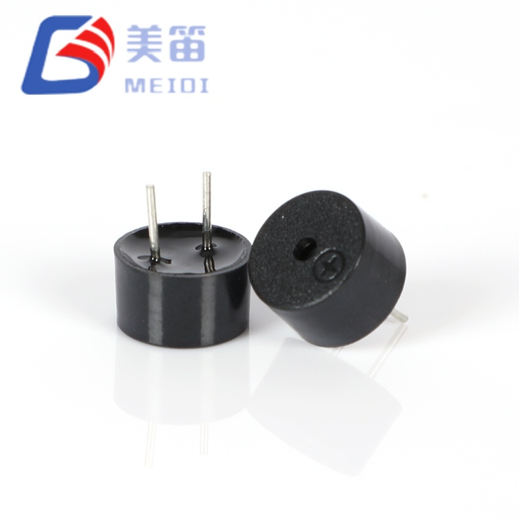
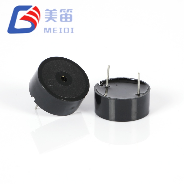
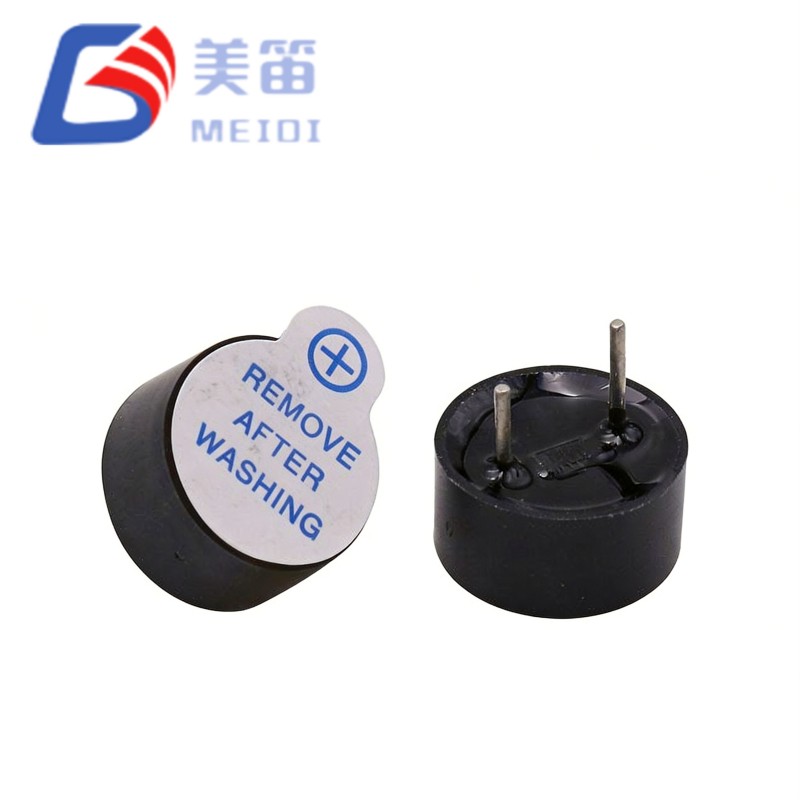
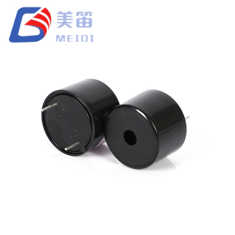
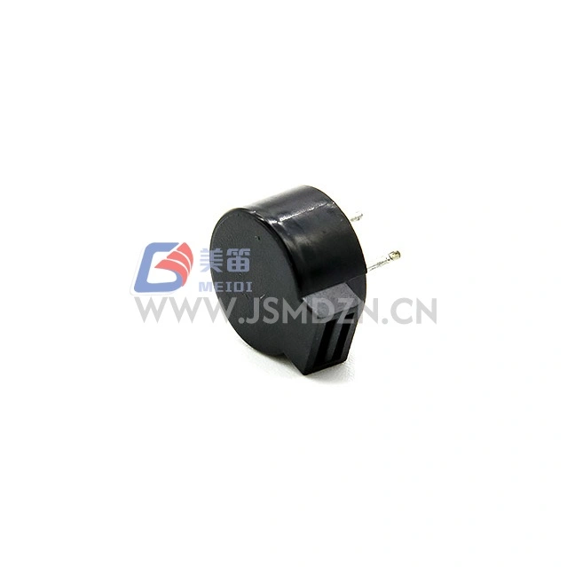
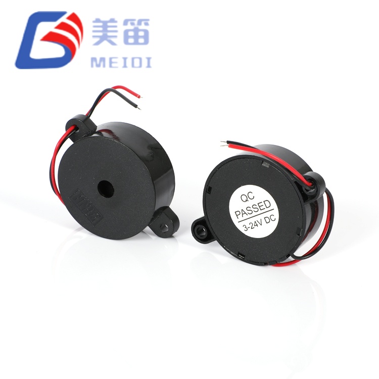
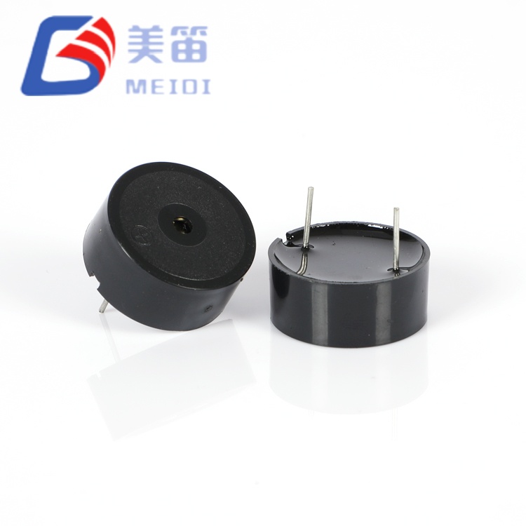
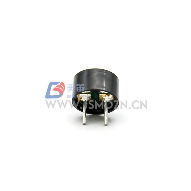
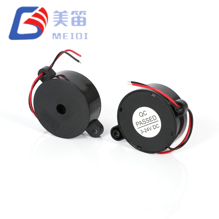
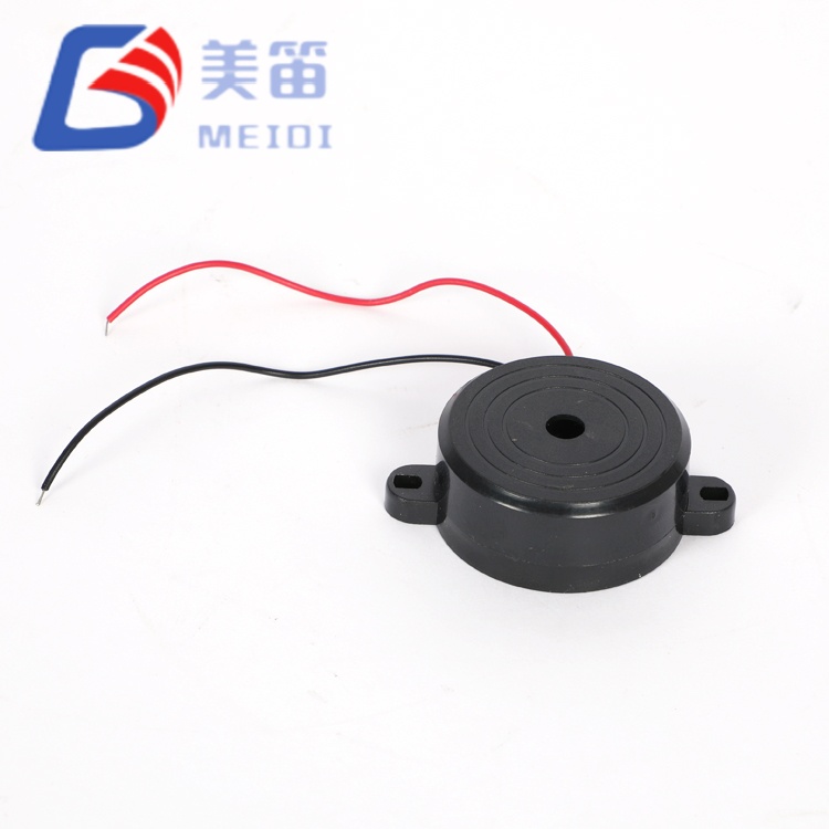
One image rule for fast pages. Keep the article light; a single product photo is enough to illustrate the part without slowing the page.
1. Buzzer Types at a Glance: Active vs Passive, Piezo vs Magnetic
Before you build any buzzer circuit, identify what you actually have. The four families behave differently on the bench, and the wiring is decided by two questions: does it have a built-in oscillator, and is the sound made by a ceramic disc or a coil?
Family
Internal oscillator?
Drive signal
Polarity
Typical current
Best use
Active piezo
Yes
DC voltage
Polarized (+ / −)
Very low
Fixed-tone alarms, timers
Passive piezo
No
AC square wave / PWM
Usually non-polar
Low (1–10 mA)
Melodies, IoT alerts
Active magnetic
Yes
DC voltage
Polarized (+ / −)
Moderate (≤30 mA)
Appliance feedback
Passive magnetic
No
Half/full square wave
Polarized (+ / −)
Higher (≤80 mA)
Industrial, SMD alarms
A clean way to tell them apart on the bench: connect the part to a 5 V DC supply. If it beeps immediately, it is active. If it stays silent, it is passive and needs a frequency source — exactly the trap that makes a first buzzer circuit look broken.
2. What You Need Before Wiring a Buzzer Circuit
A reliable buzzer circuit is built from a short, predictable bill of materials. You do not need much, but each part has a job:
Buzzer — the transducer (piezo or magnetic, active or passive).
Power source — regulated DC, typically 3 V, 5 V, or 12 V, matched to the part's rating.
Microcontroller or switch — Arduino, ESP32, or a simple push button to gate the signal.
Current-limiting resistor (100 Ω) — protects the MCU GPIO when driving a piezo directly.
NPN transistor (2N2222 / BC547) + 1 kΩ base resistor — acts as a switch for higher-current loads.
Flyback diode (1N4148) — essential across magnetic coils to absorb back-EMF.
Breadboard, jumper wires, multimeter — for assembly and troubleshooting.
3. How to Connect an Active Buzzer (Piezo & Magnetic)
An active buzzer already contains its oscillator, so the buzzer circuit is just a power switch. The trap is polarity.
3.1 Active piezo wiring
Identify the positive lead (longer wire or “+” mark). Connect it to the signal/VCC and the negative lead to GND. On an Arduino, set the pin HIGH to sound, LOW to stop. No oscillator code is needed — the internal circuit does the work.
3.2 Active magnetic wiring
The same logic applies, but a magnetic active buzzer draws more current. If it is rated under about 30 mA you can often drive it from a GPIO pin through a 100 Ω resistor; above that, use a transistor so you do not overload the microcontroller. Either way, keep the polarity correct.
Why a silent active buzzer is usually a polarity problem
If your buzzer circuit uses an active part and nothing happens, swap the leads. Active buzzers are polarized; reversing them prevents oscillation and can damage the internal IC. A passive part, by contrast, usually works either way.
4. How to Drive a Passive Buzzer (Piezo & Magnetic)
A passive buzzer has no oscillator, so the buzzer circuit must generate the tone. This is where PWM or a function generator comes in.
4.1 Passive piezo drive
Connect one lead to a PWM-capable pin and the other to GND. Use the tone(pin, frequency, duration) function on Arduino, or generate a square wave at the resonant frequency. Because a piezo is capacitive, no flyback diode is required, and a series resistor is optional but protects the pin.
4.2 Passive magnetic drive
A passive magnetic buzzer is inductive. Drive it with a square wave through a transistor, and place a 1N4148 flyback diode across the coil (cathode to the positive side). Without the diode, the collapsing magnetic field spikes voltage back into your microcontroller when the signal stops.
5. Buzzer Circuit Drive Topologies: GPIO vs Transistor vs Push-Pull
The right drive topology depends on how loud you need the buzzer circuit to be and how much current the source can supply.
Topology
Best for
Key parts
Max current
Voltage swing
Direct GPIO
Low-current active piezo / SMD
MCU pin + 100 Ω resistor
≤30 mA
Supply V
Transistor driver
Passive or 12–24 V buzzers
NPN (2N2222/BC547) + 1 kΩ base R + 1N4148 diode
~600 mA
Supply V
Push-pull (H-bridge)
Loudest output, alarms
2 transistors or TC4427 driver IC
High
2× supply V (≈ +6 dB)
For maximum SPL, a push-pull stage doubles the peak-to-peak voltage across the element, which quadruples acoustic power and adds roughly 6 dB. That is the topology used in outdoor and industrial alarm buzzers where every decibel counts.
6. Wiring an SMD Buzzer Into a PCB
Surface-mount buzzers such as the MEIDI HN-9042W (9×4.2 mm magnetic passive SMD) or MLT-1230 (piezo SMD) are placed by pick-and-place and reflowed with the rest of the board. Two rules keep the buzzer circuit reliable in production:
Follow the reflow profile. Piezo and magnetic SMD parts are heat-sensitive; stay within the recommended peak temperature and time.
Mind the acoustic cavity. A sealed back-volume behind the element can add 6–10 dB at resonance, while a flat panel mount can attenuate it. Test in the final enclosure before locking the layout.
7. Real MEIDI Buzzer Specifications
The table below uses verified parameters from the MEIDI unified catalog — no estimated values. These are the parts you would actually place when building a buzzer circuit from our range.
Most field failures in a buzzer circuit map to a short list of causes. Use this table before swapping parts in the buzzer circuit.
Symptom
Likely cause
Fix
No sound at all
Passive fed DC only, or reversed polarity on active
Use PWM for passive; check +/− on active
Weak or quiet
Driven far from resonant frequency
Drive at resonant freq (2.7–4 kHz)
Clicking only
Active buzzer driven by tone()/PWM
Feed steady DC to active buzzer
MCU resets
Back-EMF from magnetic coil / inrush
Add flyback diode + bulk cap; use transistor
Distorted tone
Wrong duty cycle or voltage mismatch
50% square wave; match rated V
9. Common Mistakes That Kill a Buzzer Circuit
Wrong signal type. Passive needs an oscillating signal; active needs DC. Mixing them is the most common silent-buzzer cause.
No flyback diode on magnetic parts. The coil's back-EMF will eventually destroy the driver pin.
Driving magnetic directly from GPIO. Current exceeds the pin's safe rating — use a transistor.
Ignoring resonance. A passive buzzer driven 500 Hz off its resonant point can drop 10–15 dB.
Overheating SMD during reflow. Follow the profile or the element depolarizes.
10. Frequently Asked Questions
Do I need a resistor with a piezo buzzer?
A standard piezo buzzer is a capacitive load and generally does not need a series current-limiting resistor the way an LED does. A small 100 ohm resistor between the MCU pin and the buzzer is still good practice to protect the GPIO. Magnetic buzzers draw steady current and need a flyback diode, and often a transistor, instead.
Can I connect a buzzer directly to an Arduino pin?
Only low-current active piezo or SMD buzzers rated below about 30 mA can be driven straight from a GPIO pin. Magnetic buzzers and passive types that need more current must use an NPN transistor or MOSFET driver plus a flyback diode, otherwise you risk damaging the microcontroller.
Should I choose an active or a passive buzzer?
Pick an active buzzer when you only need a fixed single tone and want the simplest wiring — it sounds as soon as DC power is applied. Choose a passive buzzer when you need melodies, variable pitch, or alarm patterns, because it is driven by an external square-wave or PWM signal.
Why does my passive buzzer only click instead of beep?
A passive buzzer produces sound only when it receives an oscillating signal such as a PWM square wave. If you feed it steady DC, or if the power supply browns out, you will hear a click with no tone. Use the tone() function or a frequency generator at the buzzer's resonant frequency.
What certifications should a reliable buzzer manufacturer hold?
For export-grade components you should look for ISO 9001 and ISO 14001 quality and environmental management, plus RoHS and REACH compliance for hazardous-substance restriction. MEIDI holds ISO 9001, ISO 14001, RoHS and REACH across its piezo and magnetic buzzer range.
Need verified specifications for your next design?
MEIDI is a Jiangsu buzzer manufacturer with 15 years of export experience (factory established 2011), certified to ISO 9001, ISO 14001, RoHS and REACH. Request a datasheet and quote →
We use cookies to offer you a better browsing experience, analyze site traffic and personalize content. By using this site, you agree to our use of cookies. Privacy Policy