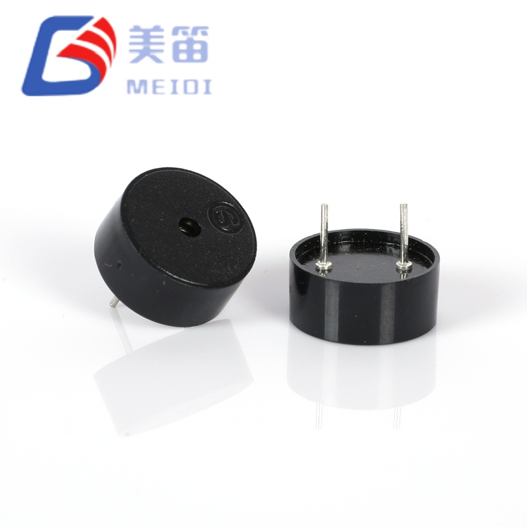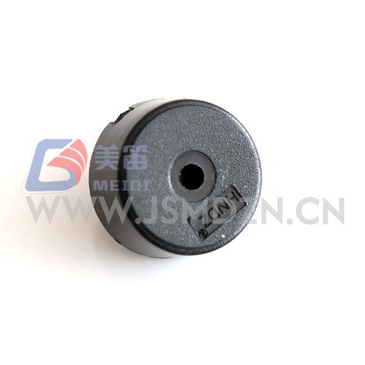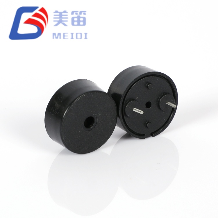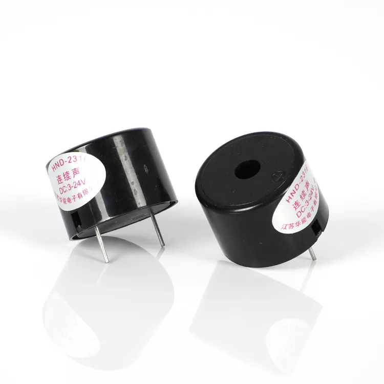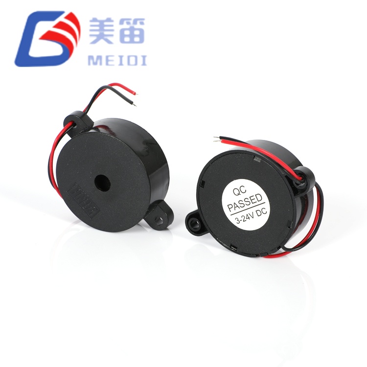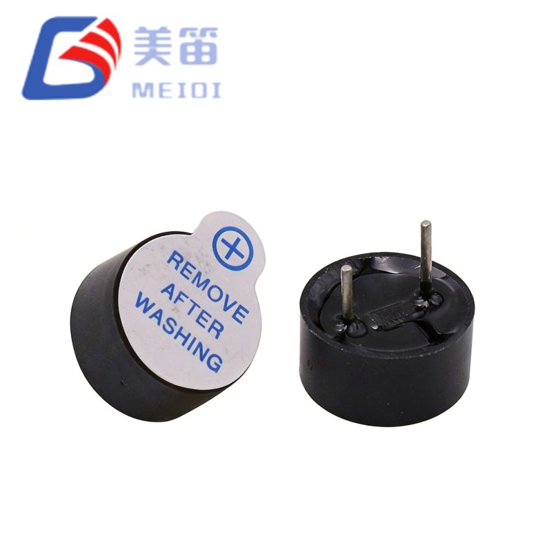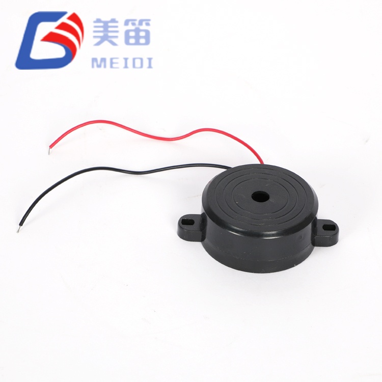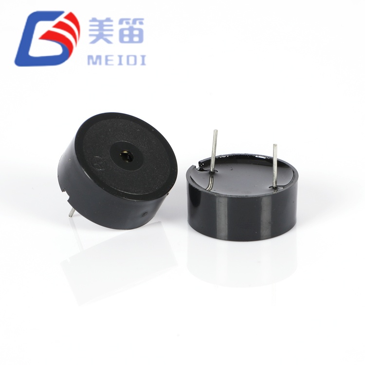
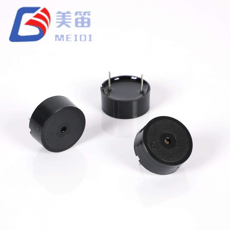
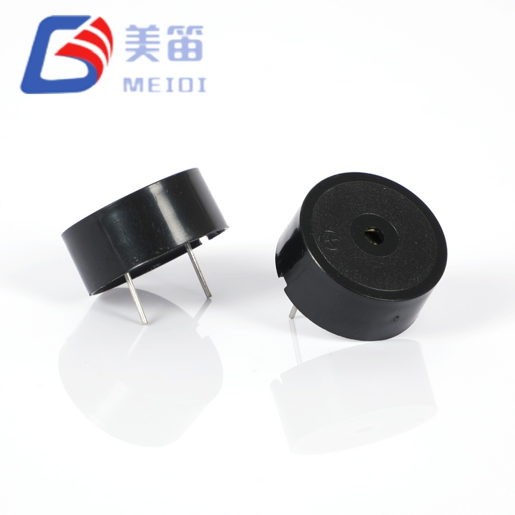
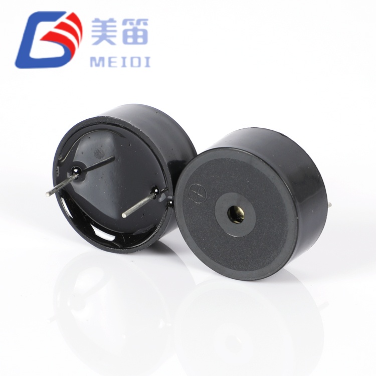
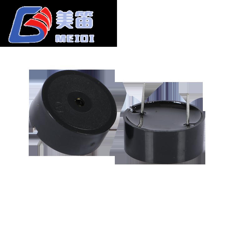
Unlike active buzzers that generate their own tone, the 23*10mm Piezoelectric Passive Buzzer is a passive piezoelectric sounder intended to be driven by an external AC waveform — typically a square wave or PWM signal supplied by a microcontroller or dedicated oscillator. Its 3500 Hz resonant frequency allows the designer to tune the driving frequency for maximum acoustic output, achieving ≥85 dB at 10 cm when fed with a 12 Vp‑p square wave. The black PBT housing measures Φ23 mm in diameter and 9.8 mm in height, making it one of the slimmer options in the HNR series. With a current draw of ≤8 mA under rated conditions and an operating voltage range of 1–30 Vp‑p, this through‑hole component suits space‑constrained designs where the host controller already provides a suitable output pin.
Passive design — requires external AC drive at 3500 Hz
12 Vp‑p rated, 1–30 Vp‑p operating range
≥85 dB SPL at 10 cm, ≤8 mA consumption at rated conditions
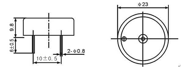
Φ23.0 × 9.8 mm black PBT through‑hole package, 3 g
Continuous operation from -20 ℃ to +70 ℃
| Parameter | Value | Test Conditions / Notes |
| Product Type | Piezoelectric Passive Buzzer | — |
| Rated Voltage | 12 Vp‑p | Peak‑to‑peak |
| Operating Voltage | 1–30 Vp‑p | Drive signal range |
| Resonant Frequency | 3500 ± 500 Hz | At rated voltage |
| Sound Output at 10 cm | ≥85 dB | 3500 Hz square wave, 12 Vp‑p |
| Current Consumption | ≤8 mA | 3500 Hz square wave, 12 Vp‑p; specification ≤8 mA; test report header may state ≤5 mA — see Test Report |
| Operating Temperature | -20 ℃ ~ +70 ℃ | Continuous |
| Storage Temperature | -30 ℃ ~ +80 ℃ | Non‑operating |
| Dimensions (Dia × H) | Φ23 ± 0.5 × 9.8 ± 0.5 mm | Body only; drawing tolerance ±0.5 mm unless specified |
| Weight | 3 g | — |
| Housing Material | Black PBT | — |
| Capacitance | 12 ± 40% nF | Reference value per specification header; not verified per sample |
| Mounting Type | Through‑Hole | Wave / Manual solder |
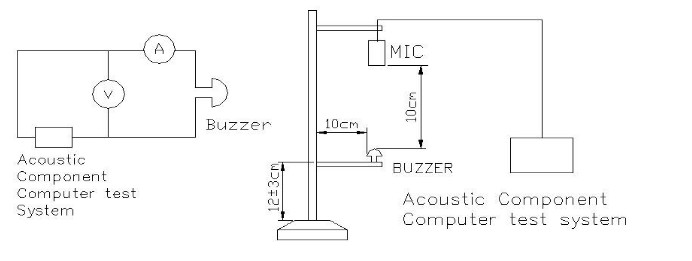
Because the 23*10mm Piezoelectric Passive Buzzer lacks an internal oscillator, the driving waveform must be supplied externally. A common approach is to use a microcontroller GPIO pin configured for PWM output at 3500 Hz with a 50% duty cycle, buffered through a transistor or dedicated driver if the pin cannot source sufficient current. The rated drive level is 12 Vp‑p, but the device operates reliably from 1 Vp‑p up to 30 Vp‑p, allowing direct connection to 3.3 V or 5 V logic after level translation when higher SPL is needed.
The specified capacitance of approximately 12 nF (reference value) should be factored into the driver stage design, as the reactive load will draw higher instantaneous currents during each edge transition. A series resistor may be added to limit peak current if the supply is sensitive, though this may reduce SPL. The frequency tolerance of ±500 Hz means the exact resonant peak can vary slightly between units; for maximum SPL, a frequency sweep during prototyping is recommended to identify the optimal drive frequency for a given batch.
Soldering is compatible with both wave (260 ℃, 4–6 s) and manual (350 ℃, 2–5 s) processes, with a 2.0 mm clearance between housing and solder bath.
| Test Item | Condition | Acceptance Criteria |
| Humidity | 50 ± 5 ℃, 90–95% RH, 48 h | All specifications satisfied after recovery |
| High Temperature | +80 ± 2 ℃, 48 h | All specifications satisfied after recovery |
| Low Temperature | -30 ± 2 ℃, 48 h | All specifications satisfied after recovery |
| Temperature Cycling | -30 ℃ ↔ +80 ℃, 30 min dwell, 5 cycles | All specifications satisfied after recovery |
| Drop | 75 cm to 10 mm hardwood, 3 drops | Appearance and electrical performance verified |
| Vibration | 10–55 Hz, 1.0 mm single amplitude, XYZ axes, 0.5 h total | No mechanical or electrical degradation |
| Solder Heat Resistance | 250 ± 5 ℃, 10 ± 0.5 s, 2.0 mm body-to-solder distance | Dimensions and performance meet specification |
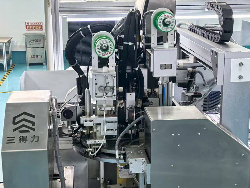
The 23*10mm Piezoelectric Passive Buzzer is assembled in the same Jiangsu facility that produces MEIDI's active buzzer range, but follows a distinct process flow owing to its passive architecture. After the piezo ceramic disc is bonded to the metal substrate and enclosed in the PBT housing, the assembly is subjected to a 100% acoustic test using a standardized 12 Vp‑p, 3500 Hz square wave to verify SPL, frequency, and current. This is supplemented by the periodic reliability sampling described above.
MEIDI's quality system, certified to ISO 9001, covers incoming material inspection, in‑process checks, and final test data logging. The facility's vertical integration — including in‑house mold making and ceramic processing — supports repeatable manufacturing outcomes and helps maintain stable lead times for both trial quantities and volume orders.


Microcontroller‑based alarm circuits where a GPIO pin can generate a 3500 Hz square wave directly, eliminating the need for a separate active buzzer module.
Portable medical devices and handheld meters that benefit from the lower 3 g weight and slim 9.8 mm profile, while the host MCU already provides the alert tone.
Industrial indicator panels with multiple sounders driven by a single multi‑channel PWM controller, using the HNR‑2310A's consistent frequency response for uniform acoustic output.
Consumer appliances and smart home sensors where the buzzer is activated only intermittently and the passive design contributes to lower standby current (no internal oscillator quiescent draw).
Educational and prototyping boards that include a PWM peripheral, allowing students and engineers to experiment with frequency‑dependent sound generation.
Ten‑sample data recorded with a 12 Vp‑p square wave at 3500 Hz shows SPL values between 91–94 dB, exceeding the ≥85 dB minimum. Current measurements range from 3.87–4.00 mA, which is below both the ≤8 mA parameter limit and the ≤5 mA figure occasionally noted in test report headers. Frequency readings fall within 3486–3600 Hz, respecting the 3500 ± 500 Hz window. Dimensions are confirmed to Φ23 × 9.8 mm tolerances.
| Sample | SPL (dB) | Current (mA) | Frequency (Hz) | Diameter (mm) | Height (mm) |
| 1 | 94 | 3.98 | 3501 | 22.92 | 10.00 |
| 2 | 92 | 4.00 | 3598 | 22.97 | 9.98 |
| 3 | 92 | 3.97 | 3486 | 23.01 | 9.89 |
| 4 | 93 | 3.99 | 3600 | 22.98 | 9.95 |
| 5 | 94 | 3.89 | 3580 | 23.03 | 9.97 |
| 6 | 91 | 3.95 | 3499 | 23.05 | 10.01 |
| 7 | 93 | 3.96 | 3510 | 22.98 | 9.99 |
| 8 | 91 | 3.88 | 3560 | 22.88 | 9.94 |
| 9 | 94 | 3.87 | 3498 | 23.00 | 9.97 |
| 10 | 94 | 3.93 | 3531 | 23.01 | 9.94 |
Conclusion: PASS. Appearance, polarity, and tape direction conform.
1. Do not apply a DC voltage directly to the HNR‑2310A; it requires an alternating waveform to generate sound. Continuous DC may overheat the piezo element.
2. The housing is not sealed. Prevent water, flux, or cleaning solvent from entering the sound port.
3. In environments with corrosive gases, protect the buzzer by placing it in a ventilated enclosure or by applying a protective coating to the terminals only.
4. Sound pressure level depends on drive voltage and waveform shape. Verify that your driver stage can achieve the desired SPL under load.
5. Keep the acoustic opening clear. Obstructions reduce output and may shift the resonant frequency.
6. Store in dry, sealed packaging until assembly to avoid pin oxidation.
1. What distinguishes a passive buzzer like the 23*10mm Piezoelectric Passive Buzzer from an active buzzer?
A passive buzzer requires an external AC drive signal at its resonant frequency, while an active buzzer contains an internal oscillator and only needs a DC supply. The HNR‑2310A gives the designer full control over the tone frequency and allows the same microcontroller pin to drive multiple sounders.
2. Can I drive the HNR‑2310A directly from a 3.3 V microcontroller pin?
Yes, as long as the 3.3 V peak‑to‑peak signal falls within the 1–30 Vp‑p operating range. However, the resulting SPL will be lower than at 12 Vp‑p. A transistor buffer or level shifter can be used to achieve higher voltage swing and louder output.
3. Why does the test report sometimes mention a current limit of ≤5 mA?
Some test report headers reference ≤5 mA, which is a documentation inconsistency. The product parameter table specifies ≤8 mA, and measured samples typically draw around 4 mA. Contact MEIDI to confirm the applicable limit for your order.
4. What is the recommended driving frequency for maximum SPL?
The nominal resonant frequency is 3500 Hz. Due to the ±500 Hz tolerance, it is advisable to sweep the driving frequency between 3000 Hz and 4000 Hz during prototyping to find the exact peak for a given unit. MEIDI can provide frequency response curves.
5. Are there any special PCB layout considerations for the HNR‑2310A?
The through‑hole footprint is standard. Ensure at least 2.0 mm clearance between the housing and the solder bath. For wave soldering, the recommended profile is 260 ℃ for 4–6 seconds.
For datasheets, drive circuit application notes, frequency sweep data, or a quotation for the HNR‑2310A, contact MEIDI with your project requirements. Engineering support typically responds within one business day.
Address
No.6, Wenlin Road, Chenbao Town, Xinghua City, Jiangsu Province, China
Tel