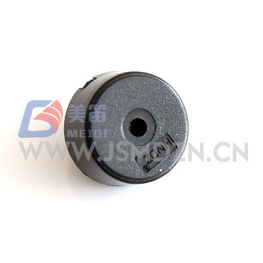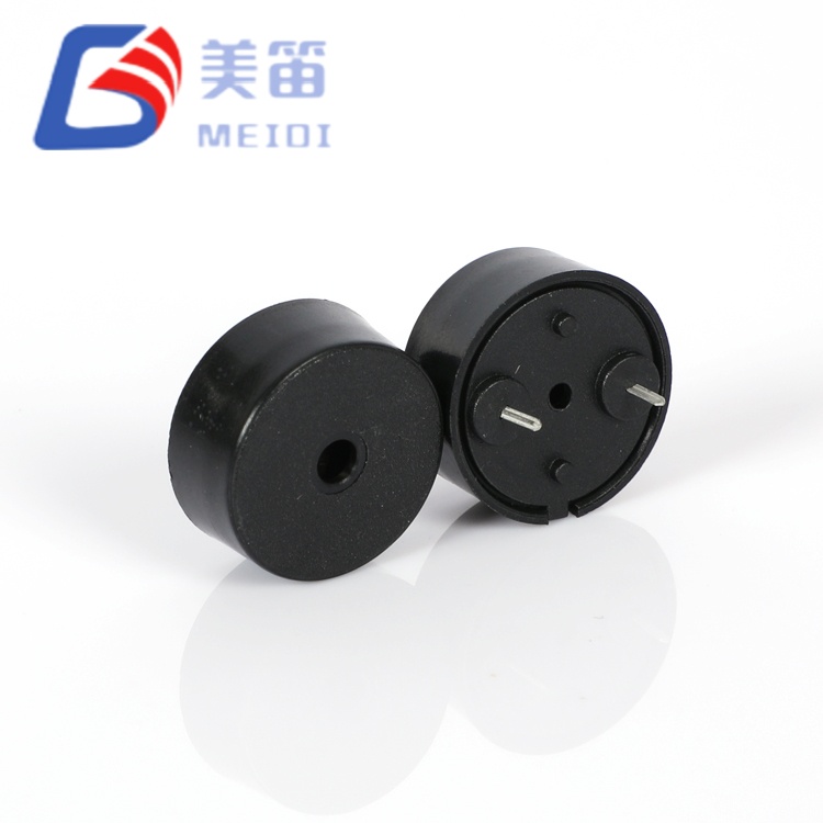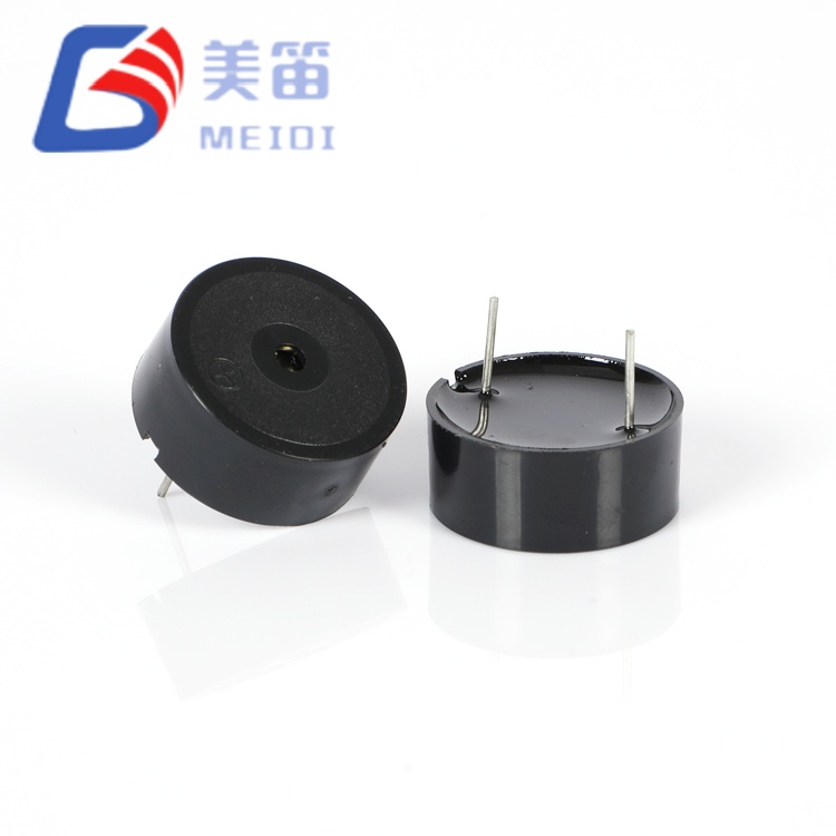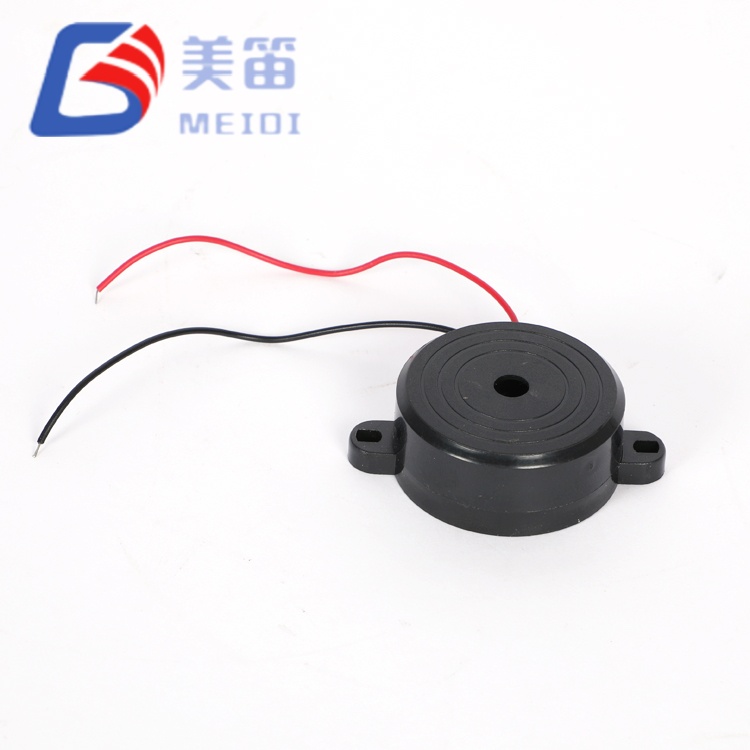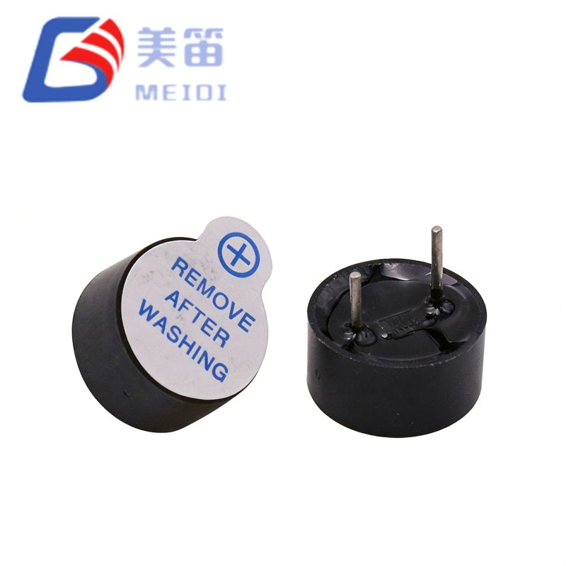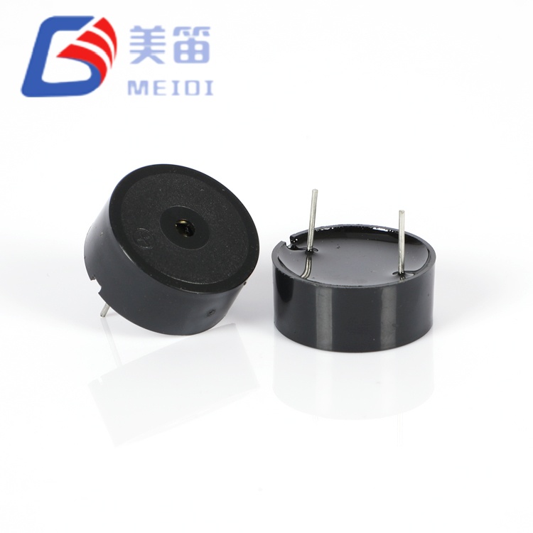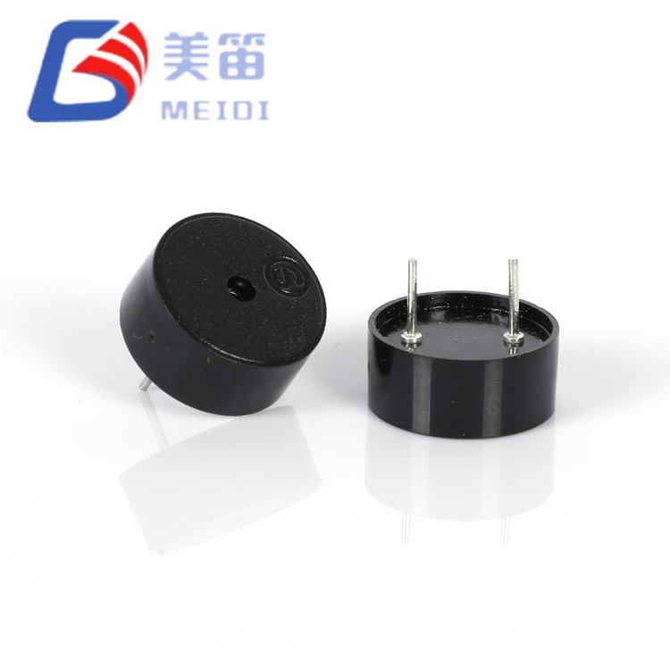
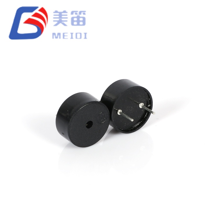
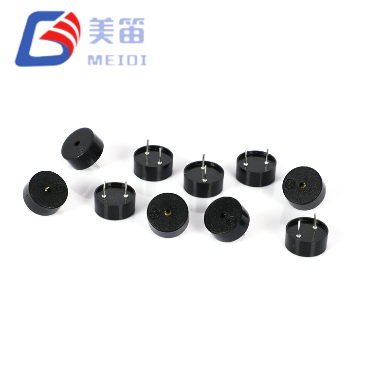
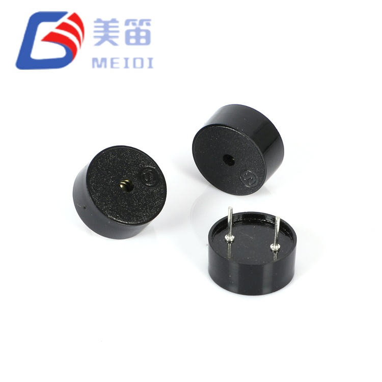
The HNR‑1255 Series comprises through‑hole piezoelectric passive buzzers engineered for systems where supply voltage varies significantly across product variants or operating conditions. With an ultra‑wide 1–30 V drive range, a single component accommodates everything from single‑cell Li‑ion batteries (3.0–4.2 V) to 5 V logic rails, 12 V automotive accessory circuits, and 24 V industrial control buses — eliminating voltage regulation circuitry and simplifying global BOM management.
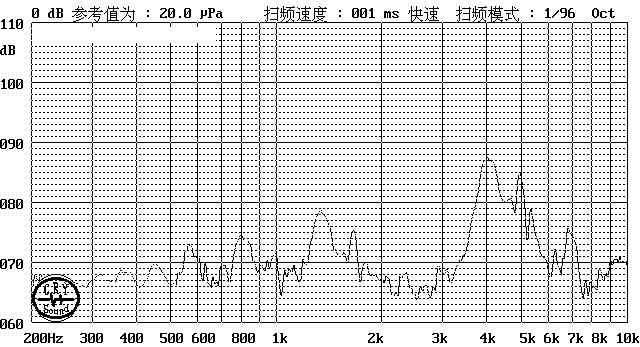
Manufactured by MEIDI in Jiangsu Province, these buzzers feature a 12.5 mm piezoelectric ceramic diaphragm — substantially larger than economy 9 mm variants — delivering ≥80 dB SPL at 4000 Hz with only ≤10 mA current draw. The 4000 Hz resonant frequency sits at the upper edge of the human auditory sensitivity peak (2–4 kHz), providing crisp, perceptible alerts with minimal power expenditure. Two mechanical variants share identical electrical performance: PA5.0 for flush PCB mounting and PA6.5 for elevated standoff or panel‑through applications.
The 12*5.5mm Piezoelectric Passive Buzzer is a 12.5 mm through-hole piezoelectric passive buzzer platform engineered for systems requiring acoustic feedback across unpredictable or variable supply voltages. Unlike conventional piezo buzzers constrained to narrow voltage windows, this series accepts drive signals from 1 V to 30 V peak-to-peak — enabling direct deployment across Li-ion battery packs, 5V logic rails, 12V automotive accessory circuits, and 24V industrial control buses without buck converters or series limiting resistors.
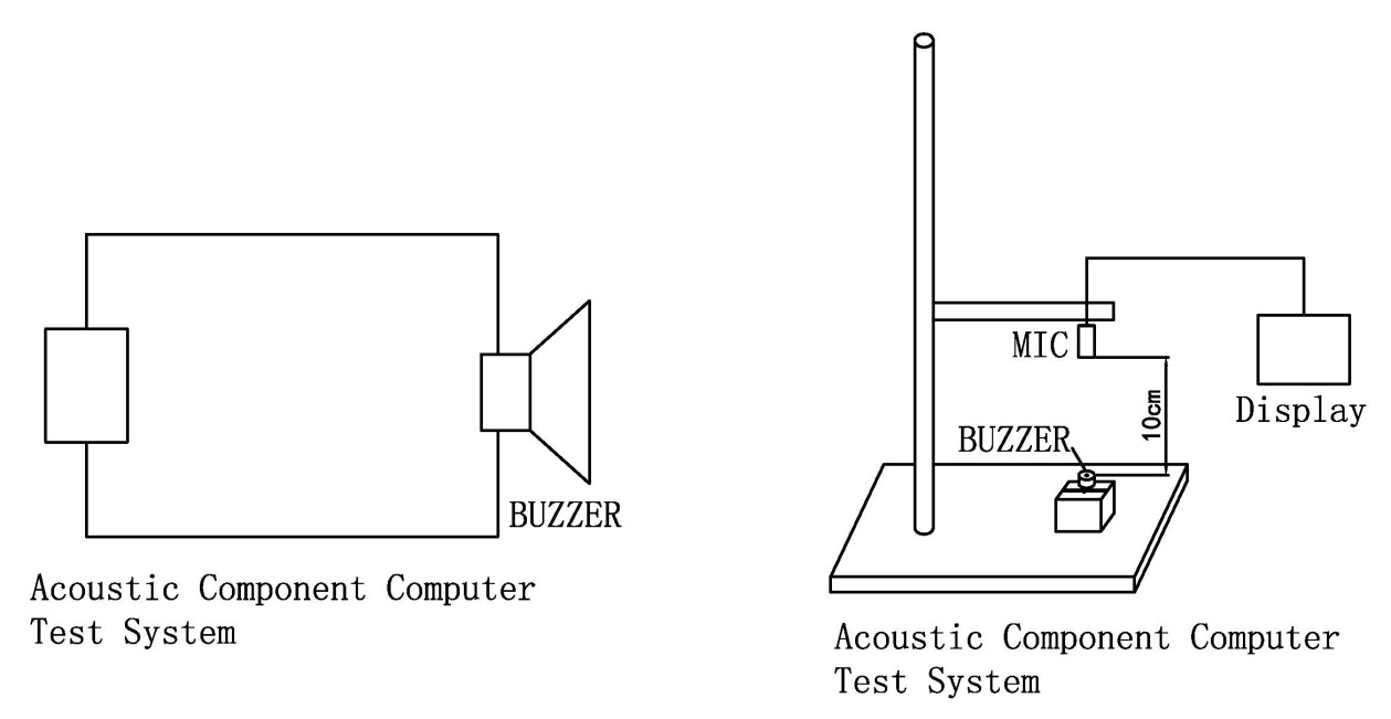
At 4000 Hz resonant frequency, the HNR-1255 Series targets the most sensitive region of human hearing (2–4 kHz), ensuring perceptibility at lower SPL thresholds than sub-2 kHz or supra-6 kHz alternatives. The 12.5 mm diameter ceramic diaphragm — substantially larger than 9 mm economy variants — generates ≥80 dB at 10 cm with only ≤10 mA current consumption, yielding exceptional acoustic efficiency for battery-powered meters, portable medical devices, and wireless sensor nodes.
Two mechanical variants share identical electrical performance: HNR-1255 PA5.0 with standard lead length for flush PCB mounting, and HNR-1255 PA6.5 with extended leads for elevated standoff applications, front-panel insertion, or conformal-coating clearance. Both variants utilize black PBT housing (UL94 V-0) and support wave soldering at 260 ℃ and manual rework at 350 ℃.
| Parameter | HNR-1255 PA5.0 | HNR-1255 PA6.5 |
| Lead Length / Standoff | 5.0 mm standard | 6.5 mm extended |
| Typical Mounting | Flush PCB surface | Elevated / panel-through |
| Resonant Frequency | 4000 ± 500 Hz | 4000 ± 500 Hz |
| Operating Voltage | 1 – 30 VDC | 1 – 30 VDC |
| Sound Output at 10 cm | ≥ 80 dB | ≥ 80 dB |
| Current Consumption | ≤ 10 mA | ≤ 10 mA |
| Capacitance | 12 ± 40% nF | 12 ± 40% nF |
| Operating Temperature | -20 ℃ ~ +70 ℃ | -20 ℃ ~ +70 ℃ |
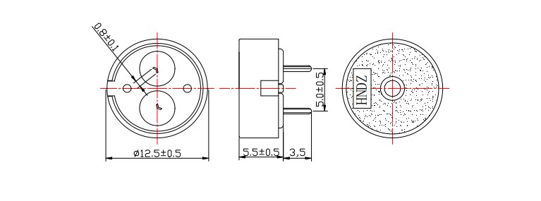
| Dimensions (Dia × H) | 12.5 × 5.5 mm | 12.5 × 5.5 mm |
| Weight | 0.60 ± 0.2 g | 0.60 ± 0.2 g |
| Housing Material | Black PBT | Black PBT |
1–30 V ultra-wide drive compatibility — eliminates voltage regulation circuitry across single-cell Li-ion (3.0–4.2V), 5V logic, 12V automotive, and 24V industrial buses
4000 Hz auditory sweet-spot resonance — positioned for maximum human perceptibility with minimal power expenditure; positioned for maximum human perceptibility with minimal power expenditure"
Sub-10 mA current draw — at 5Vp-p, 4000 Hz square wave; enables direct MCU GPIO drive and extended battery life in wireless metering
12.5 mm expanded ceramic diameter — 54% greater diaphragm area than 9 mm variants; larger area theoretically improves acoustic efficiency
Dual lead-length platform — PA5.0 and PA6.5 share one electrical BOM; mechanical selection occurs at assembly without circuit redesign
Repair-tolerant PBT housing — withstands 260 ℃ wave soldering and 350 ℃ manual rework; 10-year batch traceability via lot code marking
| Parameter | Value | Test Conditions |
| Product Type | Piezoelectric Passive Buzzer | — |
| Rated Voltage | 5 VDC | Peak-to-peak reference |
| Operating Voltage | 1 – 30 VDC | Drive signal range |
| Resonant Frequency | 4000 ± 500 Hz | At 5Vp-p, 25℃ |
| Frequency Tolerance | ±12.5% | Batch consistency |
| Sound Output | ≥ 80 dB | At 5Vp-p, 10cm, 4000Hz |
| Current Consumption | ≤ 10 mA | At 5Vp-p, 4000Hz |
| Capacitance | 12 ± 40% nF | At 1kHz, 25℃ |
| Operating Temperature | -20 ℃ ~ +70 ℃ | Continuous |
| Storage Temperature | -30 ℃ ~ +80 ℃ | Non-operating |
| Dimensions (Dia × H) | 12.5 × 5.5 mm | Body excluding pins |
| Weight | 0.60 ± 0.2 g | Typical |
| Housing Material | Black PBT | UL94 V-0 |
| Pin Diameter | 0.5 mm typical | Tin-plated copper |
| Mounting Type | Through-hole | PA5.0 / PA6.5 lead options |
•Sound Pressure: 83 – 86 dB (mean 84.3 dB)
•Current: 0.63 – 0.78 mA (mean 0.70 mA)
•Capacitance: 11.7 – 14.2 nF
•Diameter: 11.97 – 12.05 mm
•Height: 5.51 – 5.55 mm
Smart utility meters — tamper alerts, communication-failure warnings, and low-battery chirps in gas, water, and electricity meters operating from 3.6V lithium primary cells
Portable medical diagnostics — test-completion tones, calibration-status beeps, and error alerts in handheld glucose monitors and pulse oximeters
Industrial sensor networks — fault alarms and threshold notifications on 12V/24V fieldbus-powered IoT nodes and remote telemetry units
Automotive aftermarket electronics — 12V accessory bus integration for parking sensors, tire-pressure monitors, and dashcam voice prompts
Battery-management systems — overcharge, thermal-runaway, and cell-imbalance audible warnings in Li-ion pack protection circuits
Security access control — door-forced-open, invalid-badge, and low-battery alerts in standalone 12V or PoE-extracted power configurations
| Design Requirement | HNR-1255 Series Advantage |
| Uncertain final system voltage | 1–30V range spans single-cell to 24V bus; prototype with 5V, deploy at 12V without component change |
| Battery-life critical application | ≤10 mA at 5Vp-p; significantly extends battery life in continuous-tone applications |
| Human-factor alert design | 4000 Hz sits in 2–4 kHz auditory peak; positioned for maximum human perceptibility |
| Dual assembly configurations | PA5.0 for low-profile PCB; PA6.5 for panel-mount or coating-clearance needs — same electrical BOM |
| Repair and retrofit markets | Black PBT survives 350 ℃ manual soldering; pin-compatible with legacy 12 mm through-hole footprints |
The HNR-1255 Series piezoelectric element presents a capacitive load (12 nF nominal) rather than resistive. Drive circuit selection depends on voltage level and tone complexity:
| Driver Type | Voltage Range | Configuration | Recommended Variant |
| Microcontroller GPIO | 3.3V / 5V | Push-pull square wave | PA5.0; verify ≥10 mA source capability |
| Open-collector transistor | 5V / 12V | NPN with pull-up resistor | Either variant; 1 kΩ base resistor typical |
| Dedicated piezo driver IC | 5V–30V | Built-in charge pump | PA6.5 for high-voltage standoff clearance |
| Logic gate buffer | 5V | 74HC series totem-pole | PA5.0; direct frequency-accurate drive |
| Audio amplifier | 5V–30V | Sine or square wave | Either variant; verify output impedance << 1 kΩ |
Recommended drive signal: Square wave, 4000 Hz, 50% duty cycle, 5Vp-p for specification validation. SPL decreases off-resonance; output drops significantly at frequencies away from 4000 Hz.
MEIDI manufactures the 12*5.5mm Piezoelectric Passive Buzzer on dedicated piezoelectric assembly lines with statistical process control. Each production lot undergoes:
•Frequency verification — 100% resonant frequency test at 4000 Hz ±500 Hz
•SPL batch sampling — statistical sound pressure verification at 5Vp-p, 10cm
•Capacitance screening — 12 nF tolerance check for drive circuit matching
•Thermal aging — 48-hour operation at +70 ℃ maximum
•Humidity exposure — 48-hour humidity exposure per specification (50±5°C, 90-95% RH)
•Solderability verification — 260 ℃ wetting balance
Lot code marking on housing enables traceability to production date, test data, and raw material batch. Retention period: 10 years.
1. Can I drive the HNR-1255 Series directly from a 3.3V microcontroller GPIO pin?
Yes, within current limits. At 3.3Vp-p, the 12 nF capacitive load draws an estimated 6–7 mA at 4000 Hz — verify with actual measurement. SPL will be below the 5Vp-p specification; verify output with samples. For maximum output, use a 5V logic buffer or a transistor driver stage. The 1–30V operating range ensures the buzzer will not be damaged by 3.3V drive; it simply operates below rated acoustic output.
2. What is the practical difference between PA5.0 and PA6.5 in my PCB layout?
The electrical and acoustic performance is identical. The difference is mechanical: PA5.0 has standard lead length for flush mounting against the PCB surface), while PA6.5 provides extended leads for applications requiring greater standoff — such as front-panel insertion through a bezel, conformal-coating clearance, or thermal-airflow gaps. Both variants share the same PCB hole pattern and keepout zone; substitution requires no circuit or layout change.
3. How does the 4000 Hz frequency compare to 2700 Hz alternatives in real-world environments?
4000 Hz sits at the upper edge of the 2–4 kHz human auditory sensitivity peak, making it more perceptible than 2700 Hz in quiet to moderate ambient noise (offices, homes, medical facilities). However, 2700 Hz penetrates high-frequency industrial noise (motors, compressors above 3 kHz) more effectively. For indoor consumer, medical, and office environments, 4000 Hz provides crisper, more "urgent" tonal character. For factory floors and engine compartments, 2700 Hz may be preferable. The HNR-1255 Series is optimized for the former scenario.
4. Why is the capacitance tolerance ±40%, and how does this affect my driver design?
Piezoelectric ceramic capacitance varies with material batch, electrode area, and dielectric thickness. The 12 nF nominal with ±40% tolerance (7.2–16.8 nF) is typical for this class of buzzer. In practice, The sample batch measured 11.7--14.2 nF. For driver design, size the output stage for the specified capacitance tolerance range. For driver design, size the output stage for the worst-case 16.8 nF load at your switching frequency. At 4000 Hz, 16.8 nF requires ~13 mA peak charging current, still well within small-signal transistor capabilities. A 100 Ω series resistor can limit inrush current if GPIO drive is marginal.
5. Can I operate this buzzer continuously at 30V, and what is the expected lifetime?
The 30V maximum is a survival rating, not a continuous operating recommendation. At 30Vp-p, the piezoelectric element experiences maximum mechanical stress and dielectric heating. For continuous tone applications, MEIDI recommends limiting drive voltage or implementing duty cycle control to preserve electrode adhesion and ceramic integrity. Contact MEIDI for lifetime data under specific operating conditions. For continuous alarm applications, derating voltage or duty cycle extends lifetime proportionally.
For technical datasheets, drive circuit application notes, 4000 Hz acoustic characterization data, or OEM configuration discussion, submit your requirements. MEIDI applications engineering typically responds within one business day with technical documentation and volume pricing.
Address
No.6, Wenlin Road, Chenbao Town, Xinghua City, Jiangsu Province, China
Tel