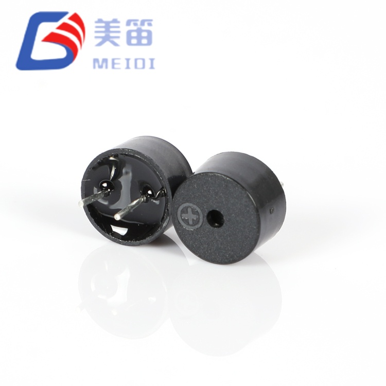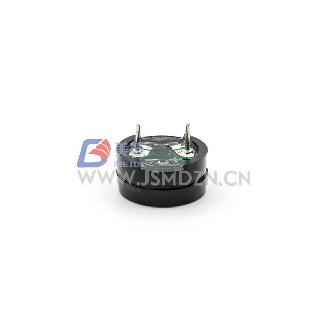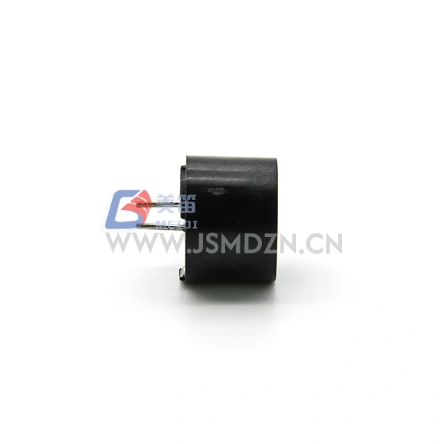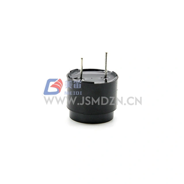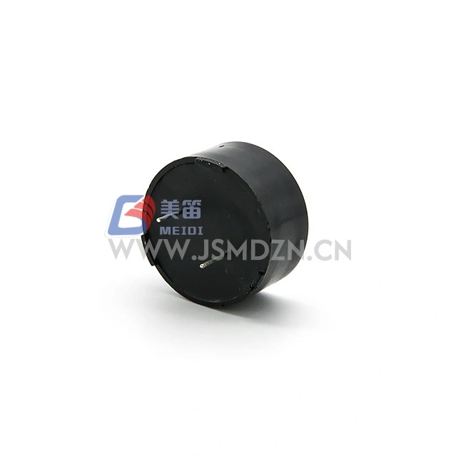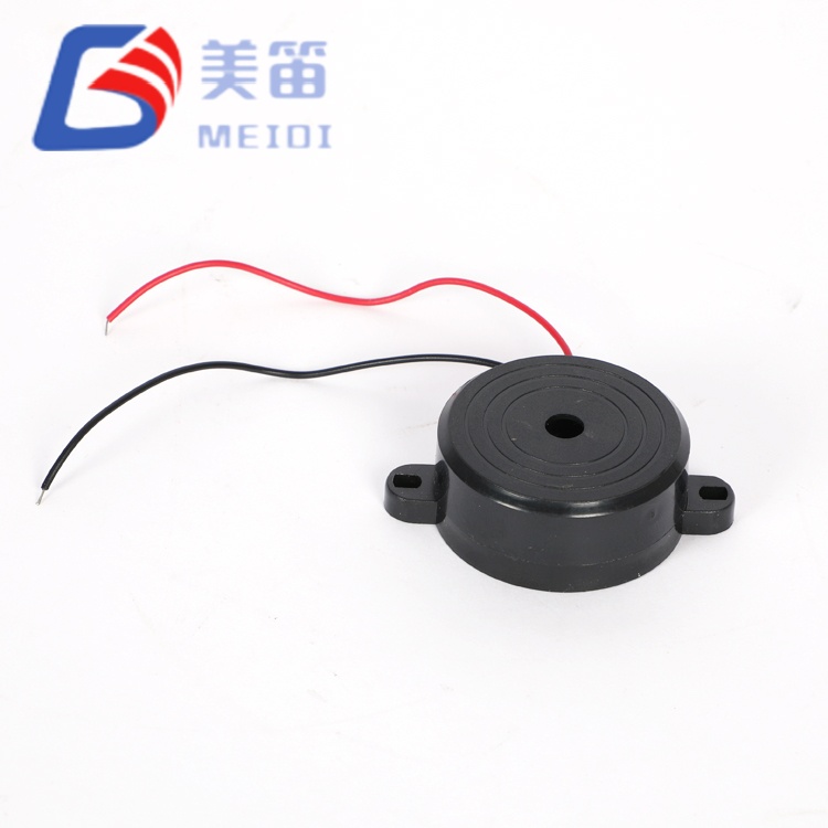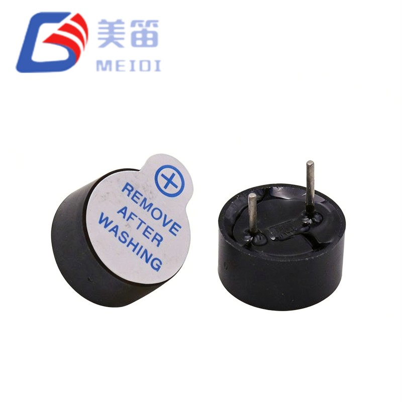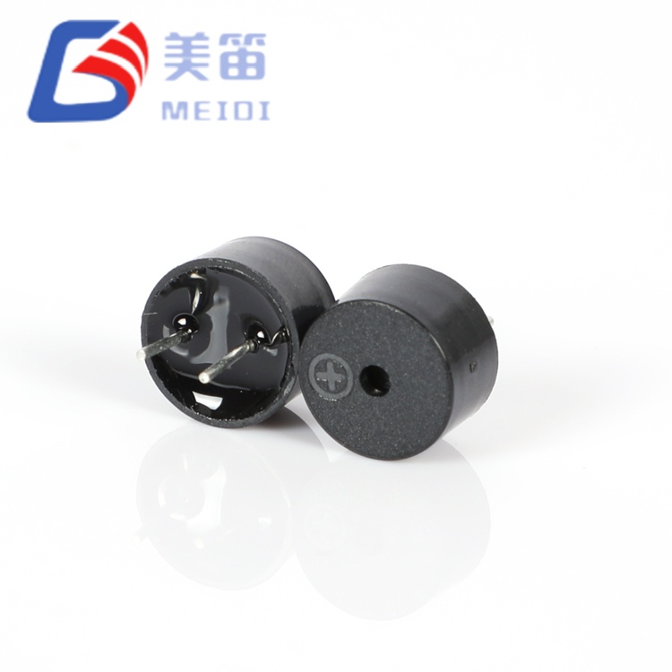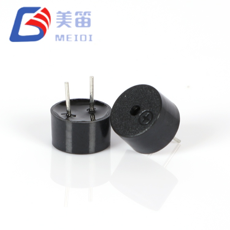
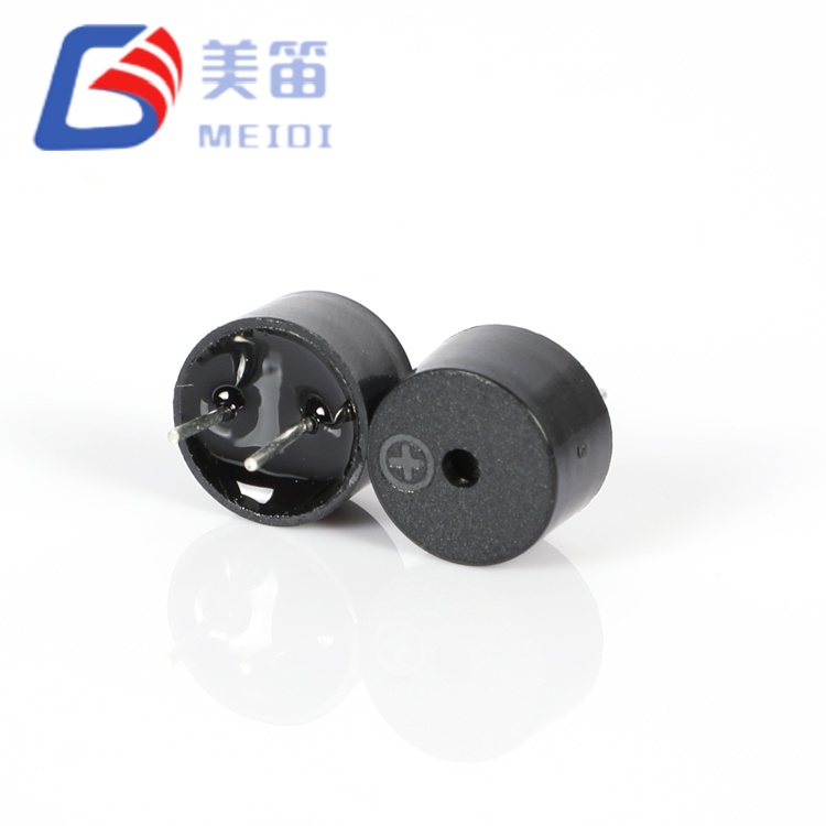
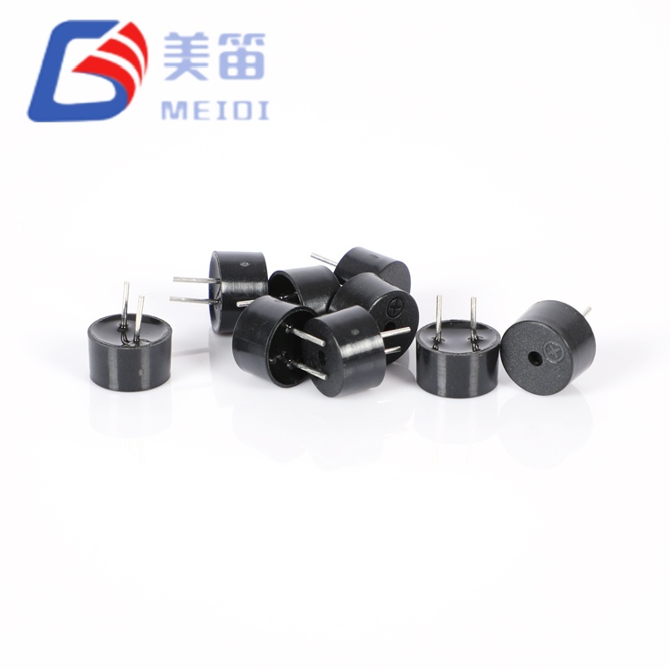
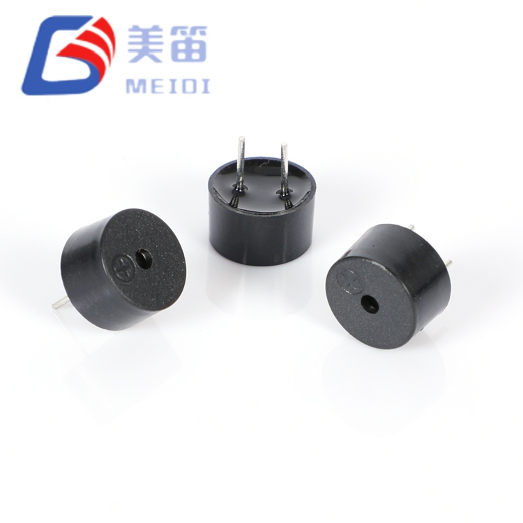
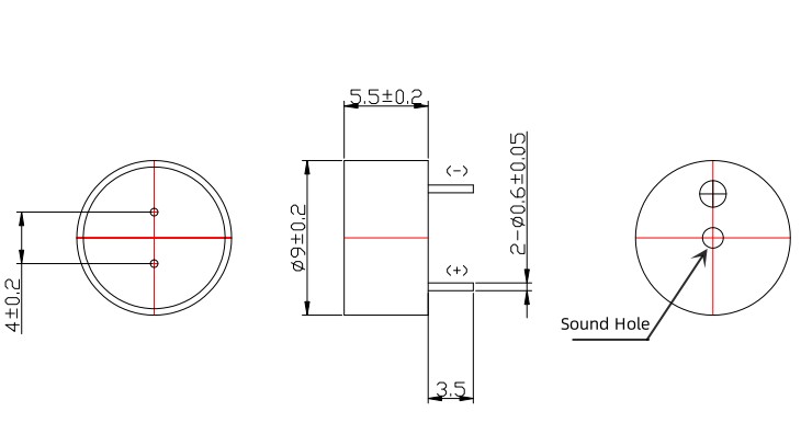
The 9*4.2mm Magnetic Passive Buzzer comprises three passive electromagnetic buzzers sharing a common 9.0 × 5.5 mm through‑hole mechanical platform, enabling voltage, impedance, and frequency selection without PCB layout changes. This family addresses a frequent procurement challenge: engineers often face trade‑offs between drive voltage, current consumption, and acoustic character that force costly mechanical redesign when the initial choice proves suboptimal.
Manufactured at MEIDI’s Jiangsu facility, these passive buzzers require external AC excitation — typically a square wave or PWM signal from a microcontroller or dedicated driver. The unified footprint means identical hole patterns, keepout zones, and enclosure acoustic models apply across all variants; only the drive circuit and BOM line item differ. The black PBT housing withstands wave soldering at 255 °C and manual rework at 360 °C, making the series suitable for both high‑volume automated assembly and legacy equipment repair.
The QMB‑09B Series resolves a common design constraint: the need to evaluate multiple drive architectures without committing to mechanical tooling changes. All three variants share identical 9.0 mm diameter, 5.5 mm height, pin spacing, and housing material — only the coil impedance, resonant frequency, and voltage rating differ.
The QMB‑09B‑03 (16 Ω, 1.5–4.5 V, 2.7 kHz) targets low‑voltage battery‑powered and logic‑level applications where direct MCU GPIO drive is preferred. Its lower coil resistance extracts more current from 3.3 V rails, producing higher SPL per volt compared to higher‑impedance alternatives at the same drive voltage.
The QMB‑09B‑05 (42 Ω, 3–7 V, 2.7 kHz) serves 5 V industrial and automotive accessory buses where reduced current draw (≤60 mA vs. ≤80 mA) eases thermal management and power supply loading. The higher impedance also provides better matching to 5 V logic outputs, reducing the risk of output stage overcurrent.
The QMB‑09B‑05 4KHZ (42 Ω, 3–7 V, 4.0 kHz) delivers the same voltage compatibility with higher‑frequency tonal character for applications where 2.7 kHz is unsuitable — such as medical devices requiring crisp alert tones, security panels needing tonal discrimination, or consumer electronics where acoustic branding matters.
All three variants share the same through‑hole pin configuration and 0.71 g mass, ensuring consistent mechanical behaviour under vibration and shock. The PBT housing is specifically formulated for through‑hole assembly environments where wave soldering and manual rework are prevalent, providing superior thermal stability compared to LCP alternatives optimised for reflow processes.
| Parameter | QMB‑09B‑03 | QMB‑09B‑05 | QMB‑09B‑05 4KHZ |
| Rated Voltage | 3 V (AC) | 5 V (AC) | 5 V (AC) |
| Operating Voltage | 1.5 – 4.5 V | 3 – 7 V | 3 – 7 V |
| Coil Resistance | 16 ± 5 Ω | 42 ± 5 Ω | 42 ± 5 Ω |
| Resonant Frequency | 2700 ± 300 Hz | 2700 ± 300 Hz | 4000 ± 300 Hz |
| Sound Output at 10 cm | ≥ 85 dB | ≥ 85 dB | ≥ 85 dB |
| Operating Current | ≤ 80 mA | ≤ 60 mA | ≤ 60 mA |
| Sample SPL Range | 87.5–94.0 dB | 91.5–94.7 dB | 91.5–94.7 dB |
| Sample Current Range | 69.2–75.5 mA | 46.8–51.7 mA | 46.8–51.7 mA |
| Drive Compatibility | 3.3 V MCU GPIO, Li‑ion | 5V logic, industrial buses | 5V logic, industrial buses |
| Typical Applications | Portable instruments, smart meters, consumer appliances | Industrial alarms, automotive accessories, PLC modules | Medical devices, security panels, tone‑discriminating systems |
Unified mechanical platform – identical 9.0 × 5.5 mm footprint and pin configuration across all variants; evaluate electrical options without PCB layout revision
Voltage‑optimised impedance pairing – 16 Ω for 3.3 V direct drive simplicity; 42 Ω for 5 V reduced‑current efficiency
Frequency‑selectable acoustics – 2.7 kHz for low‑frequency alerts; 4.0 kHz for higher‑frequency tonal clarity
Repair‑tolerant PBT housing – withstands wave soldering at 255 °C, manual soldering at 360 °C, and repeated rework without acoustic degradation
Legacy‑compatible through‑hole footprint – drop‑in replacement for obsolete 9 mm and 12 mm industry‑standard buzzers
Full batch traceability – lot code marking enables 10‑year retention of production date, test data, and raw material batch records
| Parameter | Value | Test Conditions |
| Rated Voltage | 3 V (AC) | Resonant frequency reference |
| Operating Voltage | 1.5 – 4.5 V (AC) | Drive signal peak |
| Sound Output at 10 cm | ≥ 85 dB | At 3 V, 2700 Hz, 10 cm |
| Resonant Frequency | 2700 ± 300 Hz | At rated voltage |
| Coil Resistance | 16 ± 5 Ω | At 25 ℃, DC |
| Operating Current | ≤ 80 mA | At 3 V, 2700 Hz |
| Operating Temperature | -20 ℃ ~ +70 ℃ | Continuous |
| Storage Temperature | -30 ℃ ~ +80 ℃ | Non‑operating |
| Dimension (Dia × H) | 9.0 × 5.5 mm | Body excluding pins |
| Weight | 0.71 g | Typical |
| Housing Material | Black PBT | UL94 V‑0 |
| Parameter | Value | Test Conditions |
| Rated Voltage | 5 V (AC) | Resonant frequency reference |
| Operating Voltage | 3 – 7 V (AC) | Drive signal peak |
| Sound Output at 10 cm | ≥ 85 dB | At 5 V, resonant frequency, 10 cm |
| Resonant Frequency | 2700 ± 300 Hz / 4000 ± 300 Hz | At rated voltage |
| Coil Resistance | 42 ± 5 Ω | At 25 ℃, DC |
| Operating Current | ≤ 60 mA | At 5 V |
| Operating Temperature | -20 ℃ ~ +70 ℃ | Continuous |
| Storage Temperature | -30 ℃ ~ +80 ℃ | Non‑operating |
| Dimension (Dia × H) | 9.0 × 5.5 mm | Body excluding pins |
| Weight | 0.71 g | Typical |
| Housing Material | Black PBT | UL94 V‑0 |
| Method | Temperature | Time | Max Passes |
| Reflow Soldering | 245 ± 15 ℃ | 180 ℃ preheat 40–70 s; 245 ℃ 3 s | 3 |
| Wave Soldering ★ | 255 ± 15 ℃ | 4–6 s | 2–3 |
| Manual Soldering ★ | 360 ± 10 ℃ | 2–5 s | 2–3 |
★ Recommended soldering methods for through‑hole assembly. The PBT housing provides margin above typical wave soldering temperatures, accommodating standard production profiles without acoustic degradation.
QMB‑09B‑03: Battery‑powered portable instruments, smart metering infrastructure, 3.3 V consumer appliance control boards, Li‑ion‑powered IoT sensors, handheld diagnostic tools
QMB‑09B‑05: Industrial PLC alarm modules, 5 V automotive accessory systems, commercial refrigeration controls, uninterruptible power supplies, building automation panels
QMB‑09B‑05 4KHZ: Medical diagnostic equipment requiring crisp alert tones, security intrusion panels with tonal discrimination, consumer electronics needing acoustic branding, access control systems with multiple audible cues
| Variant | Driver Type | Configuration | Notes |
| QMB‑09B‑03 | Microcontroller GPIO | Push‑pull 3.3V | Verify ≥70 mA source capability; add flyback diode |
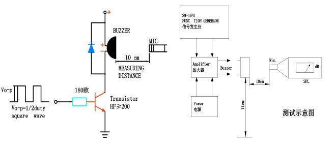
| QMB‑09B‑03 | Open‑collector transistor | NPN/PNP with pull‑up | Standard; 1 kΩ base resistor typical |
| QMB‑09B‑05 / 4KHZ | 5V logic output | Direct or buffered | 42Ω draws higher current at 5V; transistor buffer recommended |
| QMB‑09B‑05 / 4KHZ | Dedicated buzzer driver IC | Square wave output | Ensure frequency matches selected variant |
| All variants | Audio amplifier | Sine/square wave | Verify output impedance matches coil resistance |
Recommended drive signal: Square wave, at resonant frequency (2700 Hz or 4000 Hz), 50% duty cycle, at rated voltage. SPL decreases approximately 6 dB per octave away from resonance; for maximum volume, drive at the rated frequency ±5%.
| Engineering Challenge | QMB‑09B Series Solution |
| Uncertain final system voltage during prototype phase | Unified footprint allows 16Ω‑to‑42Ω or 3V‑to‑5V swap without PCB redesign |
| Need to evaluate 2.7 kHz vs 4.0 kHz tonal character | Same drive circuit, same mounting; only frequency changes |
| Legacy equipment repair with obsolete buzzer part number | 9.0 mm footprint replaces 9 mm and 12 mm legacy parts; cross‑reference available |
| Mixed assembly environment (wave + manual soldering) | PBT housing optimised for through‑hole thermal profiles; withstands repeated rework |
| Supply chain simplification across multiple projects | Single mechanical SKU family reduces inventory and qualification overhead |
The 0.71 g mass and standardised 9.0 mm diameter ensure mechanical compatibility with existing front‑panel cutouts and PCB layouts. Sample batch data across all variants confirms parameters within specification windows: SPL 87.5–94.7 dB, current 46.8–75.5 mA depending on variant.
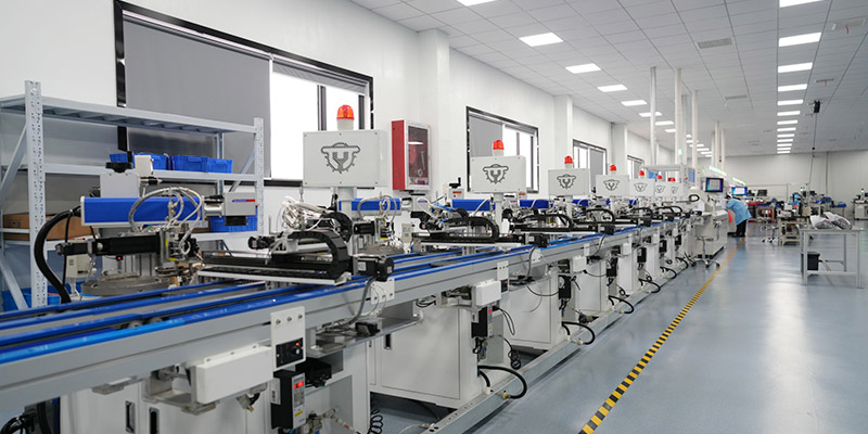
MEIDI produces the QMB‑09B Series on dedicated through‑hole assembly lines with automated winding, soldering, and inspection stations. Our Jiangsu manufacturing base follows ISO 9001 protocols, with in‑process controls at every production stage. Each batch carries a lot code marking on the housing, enabling 10‑year traceability to production date, test records, and raw material certificates.

Batch‑level qualification includes:
Coil resistance 100% test – tolerance verification per variant specification (16 Ω ±5 Ω or 42 Ω ±5 Ω)
Resonant frequency spot check – statistical sampling at rated frequency ±11%; typical measured range 2650–2740 Hz for 2.7 kHz variants
SPL batch verification – ≥85 dB minimum at rated conditions; sample mean typically 90–93 dB
Current draw validation – ≤80 mA (QMB‑09B‑03) or ≤60 mA (QMB‑09B‑05 variants) at rated voltage
Solderability per J‑STD‑002 – category 3, 260 °C wetting balance with full lead coverage
RoHS and REACH compliance – full material declaration and certificate available upon request
Thermal shock cycling – 5 cycles between -30 °C and +80 °C with 30‑minute dwell per extreme, verifying structural integrity of the PBT housing and internal connections
Q1: How do I select between QMB‑09B‑03, QMB‑09B‑05, and QMB‑09B‑05 4KHZ?
Selection is driven by your available drive voltage, current budget, and acoustic preference. The QMB‑09B‑03 (16 Ω, 1.5–4.5 V) is optimised for 3.3 V logic and Li‑ion battery systems where direct MCU GPIO drive is desired. Its lower coil resistance extracts more current from 3.3 V rails, producing higher SPL per volt than the 42 Ω variant at the same drive voltage. The QMB‑09B‑05 (42 Ω, 3–7 V) targets 5 V industrial and automotive buses where reduced current draw (≤60 mA vs. ≤80 mA) matters for thermal management and power supply loading. The 4 kHz variant delivers the same voltage compatibility with higher‑frequency tonal clarity for applications where 2.7 kHz is too low or masked by ambient noise.
Q2: Can I use QMB‑09B‑03 in a 5 V system, or QMB‑09B‑05 in a 3.3 V system?
Not recommended without modification. The QMB‑09B‑03 is rated for maximum 4.5 V; applying 5 V risks coil overheating and may exceed the ≤80 mA specification. The QMB‑09B‑05 minimum operating voltage is 3 V; at 3.3 V the 42 Ω coil produces reduced output below rated specification. For 5 V systems requiring 16 Ω drive characteristics, add a series resistor (typically 47–100 Ω) to limit current to safe levels. For 3.3 V systems requiring 42 Ω characteristics, consider the QMB‑09B‑03 instead, or evaluate whether a 5 V supply can be routed to the buzzer separately.
Q3: What is the practical difference between 2.7 kHz and 4.0 kHz in typical environments?
2.7 kHz provides lower‑frequency penetration that cuts through mechanical ambient noise common in factory floors, vehicle cabins, and machinery enclosures. 4.0 kHz delivers higher‑frequency tonal character with strong perceptibility in quieter indoor environments such as medical facilities, offices, and consumer settings. In outdoor applications, 2.7 kHz propagates with less atmospheric attenuation over distance. Both frequencies are equally manufacturable with identical reliability and lifetime characteristics; selection is an acoustic preference and ambient noise consideration.
Q4: Are custom lead lengths, alternative pin forming, or tape‑and‑reel packaging available?
Yes. MEIDI supports custom lead trimming (straight, kinked, offset, or vertical forming) for non‑standard PCB layouts or height‑constrained enclosures. Tape‑and‑reel packaging is not standard for through‑hole buzzers but can be arranged for high‑volume automated insertion with minimum order quantities. Custom lead forming typically adds 2–4 weeks to lead time depending on volume and complexity. Submit an OEM configuration request for quotation and feasibility assessment.
Q5: Can I drive these buzzers with a frequency other than the rated resonance?
SPL decreases when driven away from resonance — output drops approximately 6 dB per octave off‑resonance. For maximum volume, drive at the rated frequency (2700 Hz or 4000 Hz) ±5%. For multi‑tone or musical applications requiring broad frequency response, consider a piezoelectric buzzer or miniature speaker instead. The QMB‑09B series is optimised for fixed‑frequency alert tones where maximum SPL per watt is the primary requirement.
Q6: What is the expected acoustic lifetime under continuous drive at rated voltage?
The QMB‑09B series is a passive component; lifetime depends on drive signal duty cycle, ambient temperature, and voltage. The standard qualification includes 96 hours continuous drive at rated voltage with 1/2 duty cycle square wave at 25 °C. For extended continuous‑tone applications, reducing duty cycle (e.g., 1 second on, 4 seconds off) extends lifetime and reduces coil heating. Contact factory engineering for application‑specific lifetime estimates under your operating conditions.
For cross‑reference verification with legacy buzzer part numbers, series datasheets, sample evaluation of all three variants, or custom lead configurations, contact MEIDI Replacement Parts Division.
MEIDI replacement engineering typically responds to compatibility inquiries within one business day with pinout drawings, driver circuit notes, and volume pricing for repair and new production programs.
Address
No.6, Wenlin Road, Chenbao Town, Xinghua City, Jiangsu Province, China
Tel