English


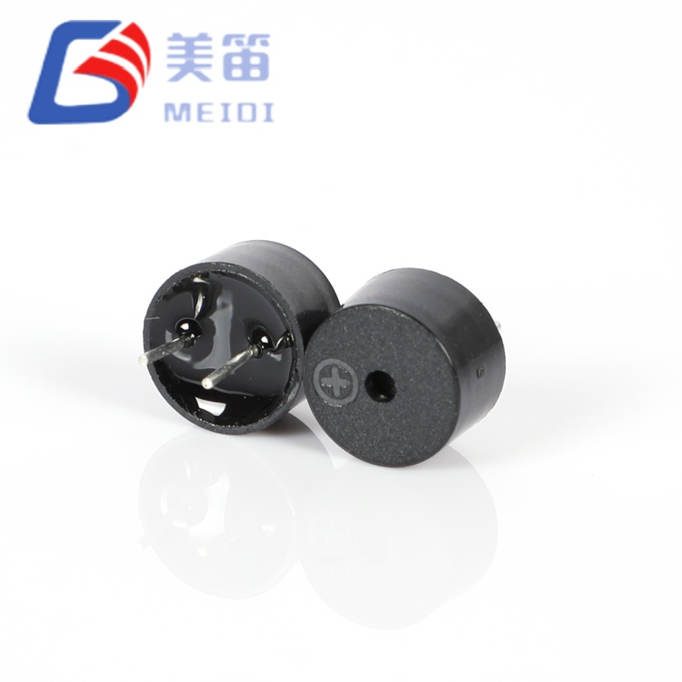
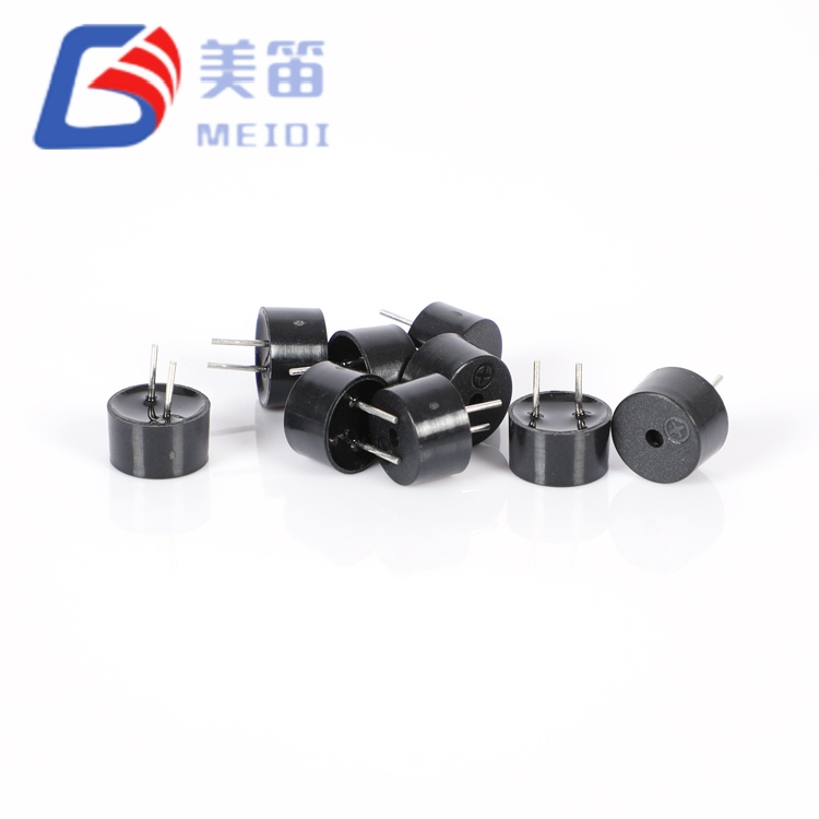
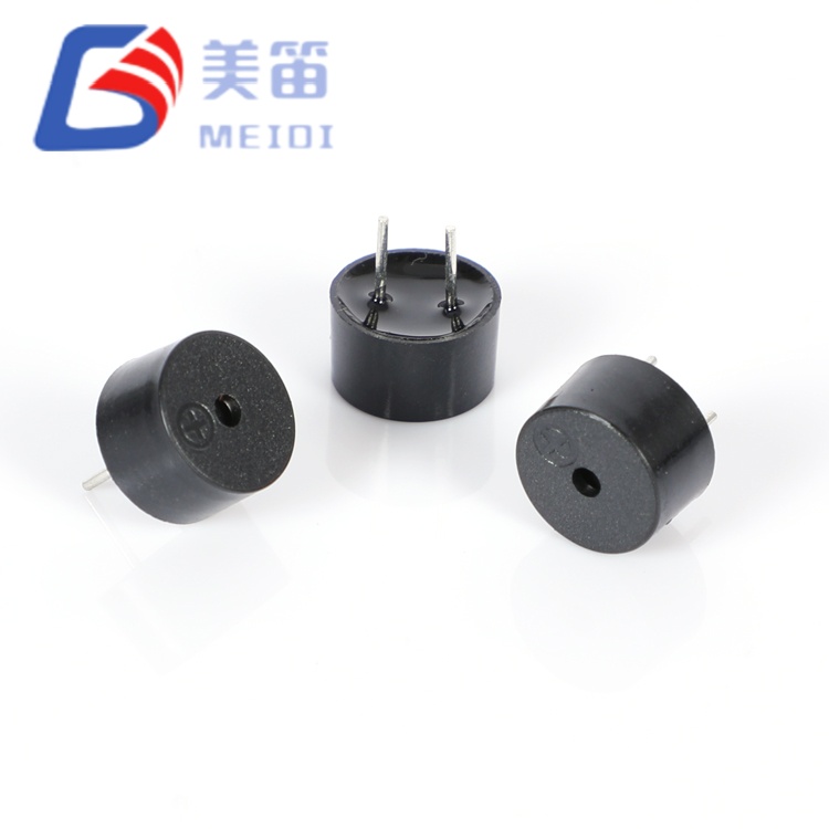
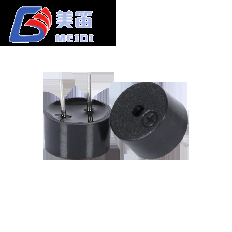
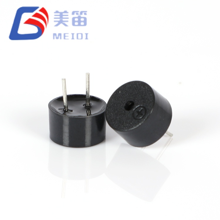
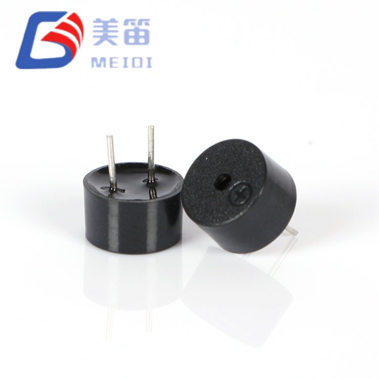
The 9*5.5mm Magnetic Passive Buzzer three through‑hole passive electromagnetic buzzers under a single 9.0 × 5.5 mm mechanical platform. Two coil resistances and two resonant frequencies let designers match the buzzer to the supply voltage and tonal requirement without altering the PCB hole pattern. The 16 Ω variant runs from 1.5 V to 4.5 V for 3.3 V logic and lithium‑ion systems; the 42 Ω variants cover 3 V to 7 V for industrial 5 V rails. Across all three models, sound pressure exceeds 85 dB at 10 cm, and the black PBT body is optimised for wave and manual soldering in mixed‑process assembly.
Three electrical profiles from a single 9.0 × 5.5 mm footprint; no layout change needed when switching between 3 V and 5 V architectures.
The 16 Ω, 3 V, 2.7 kHz model suits battery‑powered and logic‑level devices where direct microcontroller drive is preferred.
The 42 Ω, 5 V, 2.7 kHz model reduces current draw on standard industrial and automotive accessory buses.
The 42 Ω, 5 V, 4.0 kHz model provides the same electrical interface with a higher‑frequency tone for applications that benefit from a crisper alert.
All variants share the same through‑hole pin spacing, so repair and retrofit projects can replace obsolete 9 mm and 12 mm buzzers without board modification.
Minimum sound pressure is 85 dB at 10 cm across the series; production samples typically reach 87 dB to 95 dB.
| Parameter | QMB‑09B‑03 | QMB‑09B‑05 | QMB‑09B‑05 4KHZ |
| Rated Voltage | 3 V (AC) | 5 V (AC) | 5 V (AC) |
| Operating Voltage | 1.5 – 4.5 V | 3 – 7 V | 3 – 7 V |
| Coil Resistance | 16 ± 5 Ω | 42 ± 5 Ω | 42 ± 5 Ω |
| Resonant Frequency | 2700 ± 300 Hz | 2700 ± 300 Hz | 4000 ± 300 Hz |
| Sound Output at 10 cm | ≥ 85 dB | ≥ 85 dB | ≥ 85 dB |
| Operating Current | ≤ 80 mA | ≤ 60 mA | ≤ 60 mA |
| Sample SPL Range | 87.5–94.0 dB | 91.5–94.7 dB | 91.5–94.7 dB |
| Sample Current Range | 69.2–75.5 mA | 46.8–51.7 mA | 46.8–51.7 mA |
| Drive Compatibility | 3.3 V MCU GPIO, Li‑ion | 5V logic, industrial buses | 5V logic, industrial buses |
| Typical Applications | Portable instruments, smart meters, consumer appliances | Industrial alarms, automotive accessories, PLC modules | Medical devices, security panels, tone‑discriminating systems |
A single mechanical design covers three electrical variants, allowing the drive architecture to be finalised without changing the PCB hole layout.
The 16 Ω coil is matched to 3.3 V supplies, keeping the driver stage simple; the 42 Ω coil lowers current on 5 V rails.
Two resonant frequencies are available: 2.7 kHz for low‑frequency noise penetration, and 4.0 kHz for a sharper tonal quality.
The black PBT housing tolerates wave soldering at 255 °C and manual rework at 360 °C without deformation or acoustic shift.
The 9.0 mm diameter and standard pin pitch make the series a drop‑in replacement for many legacy 9 mm and 12 mm through‑hole buzzers.
Every unit carries a lot code that links back to production date, test records and raw material batches, maintained for ten years.
| Parameter | Value | Test Conditions |
| Rated Voltage | 3 V (AC) | Resonant frequency reference |
| Operating Voltage | 1.5 – 4.5 V (AC) | Drive signal peak |
| Sound Output at 10 cm | ≥ 85 dB | At 3 V, 2700 Hz, 10 cm |
| Resonant Frequency | 2700 ± 300 Hz | At rated voltage |
| Coil Resistance | 16 ± 5 Ω | At 25 ℃, DC |
| Operating Current | ≤ 80 mA | At 3 V, 2700 Hz |
| Operating Temperature | -20 ℃ ~ +70 ℃ | Continuous |
| Storage Temperature | -30 ℃ ~ +80 ℃ | Non‑operating |
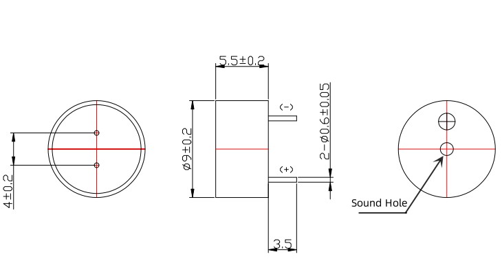
| Dimension (Dia × H) | 9.0 × 5.5 mm | Body excluding pins |
| Weight | 0.71 g | Typical |
| Housing Material | Black PBT | UL94 V‑0 |
| Parameter | Value | Test Conditions |
| Rated Voltage | 5 V (AC) | Resonant frequency reference |
| Operating Voltage | 3 – 7 V (AC) | Drive signal peak |
| Sound Output at 10 cm | ≥ 85 dB | At 5 V, resonant frequency, 10 cm |
| Resonant Frequency | 2700 ± 300 Hz / 4000 ± 300 Hz | At rated voltage |
| Coil Resistance | 42 ± 5 Ω | At 25 ℃, DC |
| Operating Current | ≤ 60 mA | At 5 V |
| Operating Temperature | -20 ℃ ~ +70 ℃ | Continuous |
| Storage Temperature | -30 ℃ ~ +80 ℃ | Non‑operating |
| Dimension (Dia × H) | 9.0 × 5.5 mm | Body excluding pins |
| Weight | 0.71 g | Typical |
| Housing Material | Black PBT | UL94 V‑0 |
| Method | Temperature | Time | Max Passes |
| Reflow Soldering | 245 ± 15 ℃ | 180 ℃ preheat 40–70 s; 245 ℃ 3 s | 3 |
| Wave Soldering ★ | 255 ± 15 ℃ | 4–6 s | 2–3 |
| Manual Soldering ★ | 360 ± 10 ℃ | 2–5 s | 2–3 |
★ Preferred methods for through‑hole assembly. The PBT housing maintains dimensional stability across these profiles, preventing terminal loosening or acoustic cavity distortion.
QMB‑09B‑03: handheld instruments, smart utility meters, 3.3 V consumer appliance control boards and Li‑ion‑powered IoT sensors where a single‑cell supply and direct GPIO drive are desirable.
QMB‑09B‑05: industrial PLC alarm modules, 5 V automotive accessory circuits, commercial refrigeration controllers and uninterruptible power supplies that benefit from lower coil current.
QMB‑09B‑05 4KHZ: medical diagnostic equipment, security intrusion panels, tone‑discriminating alarm networks and consumer products that require a higher‑pitched alert.
| Variant | Driver Type | Configuration | Notes |
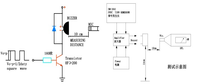
| QMB‑09B‑03 | Microcontroller GPIO | Push‑pull 3.3V | Confirm the pin can source at least 70 mA; add a flyback diode across the coil. |
| QMB‑09B‑03 | Open‑collector transistor | NPN/PNP with pull‑up | A 1 kΩ base resistor is a typical starting value. |
| QMB‑09B‑05 / 4KHZ | 5V logic output | Direct or buffered | The 42 Ω coil draws less current; a transistor buffer is still recommended for long cable runs. |
| QMB‑09B‑05 / 4KHZ | Dedicated buzzer driver IC | Square wave output | Match the output frequency to the buzzer’s rated resonance for maximum volume. |
| All variants | Audio amplifier | Sine or square wave | Ensure the amplifier’s output impedance is compatible with the coil resistance. |
A 50 % duty‑cycle square wave at the resonant frequency (2.7 kHz or 4.0 kHz) and rated voltage yields the specified sound pressure. Off‑resonance drive reduces output by approximately 6 dB per octave.
| Design Situation | QMB‑09B Series Advantage |
| Final system voltage not yet fixed | One footprint accepts 16 Ω or 42 Ω variants, so the PCB design can proceed while the supply rail is being confirmed. |
| Need to evaluate 2.7 kHz against 4.0 kHz | Same drive circuit and mounting, only the part number changes during acoustic testing. |
| Repairing legacy equipment with an obsolete buzzer | The 9.0 mm diameter and standard pin pitch often match 9 mm and 12 mm through‑hole buzzers directly. |
| Wave soldering and manual rework on the same line | The PBT body is selected specifically for these thermal profiles, remaining dimensionally stable and acoustically consistent. |
| Reducing supplier count | Three electrical configurations are covered by a single mechanical family, lowering qualification and inventory workload. |
At 0.71 g, the buzzer adds minimal mass to the board, and the established pin layout speeds up integration. Sample data confirms that all parameters sit comfortably within the published windows.
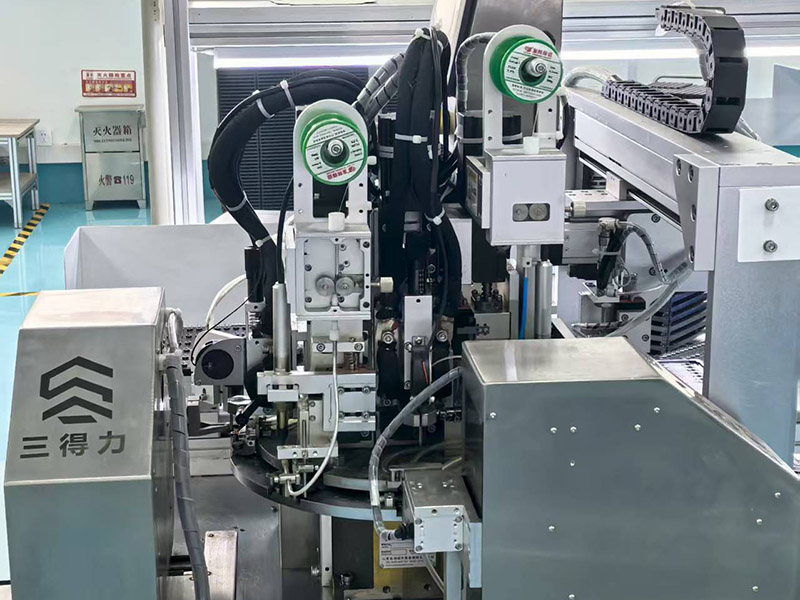
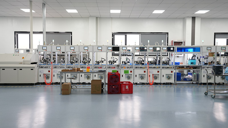
MEIDI Intelligent Technology has been producing electromagnetic and piezoelectric acoustic components since 2011. The company’s vertically integrated factory in Jiangsu, China, covers in‑house PBT moulding, precision coil winding, automated assembly and full inline acoustic testing. An ISO 9001‑certified quality system and a dedicated reliability laboratory support the consistency required by high‑volume industrial and automotive programmes.
Every production batch of the QMB‑09B series undergoes 100 % coil resistance verification and statistical checks of resonant frequency. Sound pressure level is confirmed against the 85 dB minimum, and solderability is tested per J‑STD‑002. RoHS and REACH compliance are maintained, with full material declarations available. A lot code marked on the housing provides traceability back to the production date, test records and raw material batch for ten years.

Q1: How do I choose between the three models?
Start with your available voltage. For 3.3 V logic or single‑cell lithium‑ion, the QMB‑09B‑03 (16 Ω) is the natural fit. For 5 V industrial or automotive rails, the QMB‑09B‑05 or QMB‑09B‑05 4KHZ (both 42 Ω) reduce current demand. Then choose the tone: 2.7 kHz for low‑frequency alert penetration, 4.0 kHz for a brighter, more distinctive sound. All three share the same footprint, so a late change is straightforward.
Q2: Can the QMB‑09B‑03 be used at 5 V, or the 42 Ω parts at 3.3 V?
Operating the 16 Ω model above 4.5 V may overheat the coil. The 42 Ω model below 3 V will produce a significantly lower sound level. If you need 16 Ω at 5 V, add a series resistor to limit current; the SPL will still drop. For 3.3 V systems requiring a higher impedance, the 16 Ω variant is the better match.
Q3: What is the practical difference between 2.7 kHz and 4.0 kHz in a real environment?
2.7 kHz tends to cut through low‑frequency mechanical noise, making it suitable for factory floors and outdoor equipment. 4.0 kHz sits closer to the peak of human hearing sensitivity, giving a crisp, easily discriminated tone for indoor medical, security and consumer devices. Both are equally robust and reliable.
Q4: Are custom lead lengths or tape‑and‑reel packaging available?
Yes. MEIDI can supply straight, kinked or offset lead forming for non‑standard PCB layouts. Tape‑and‑reel is not standard for through‑hole parts but can be arranged for automated insertion lines. Minimum order quantities and lead times vary depending on the modification.
Q5: Can I drive the buzzer away from its resonant frequency for a different tone?
The sound level drops noticeably when the drive frequency moves away from resonance. For maximum volume, stay within ±5 % of the rated 2700 Hz or 4000 Hz. If your application needs a wide range of frequencies, a piezoelectric buzzer or miniature speaker would be a more suitable choice.
For cross‑reference verification against legacy part numbers, evaluation samples of all three variants, or custom lead configurations, contact the MEIDI replacement parts team. Compatibility queries typically receive a response within one business day, together with pinout drawings and drive circuit notes.
Address
No.6, Wenlin Road, Chenbao Town, Xinghua City, Jiangsu Province, China
Tel