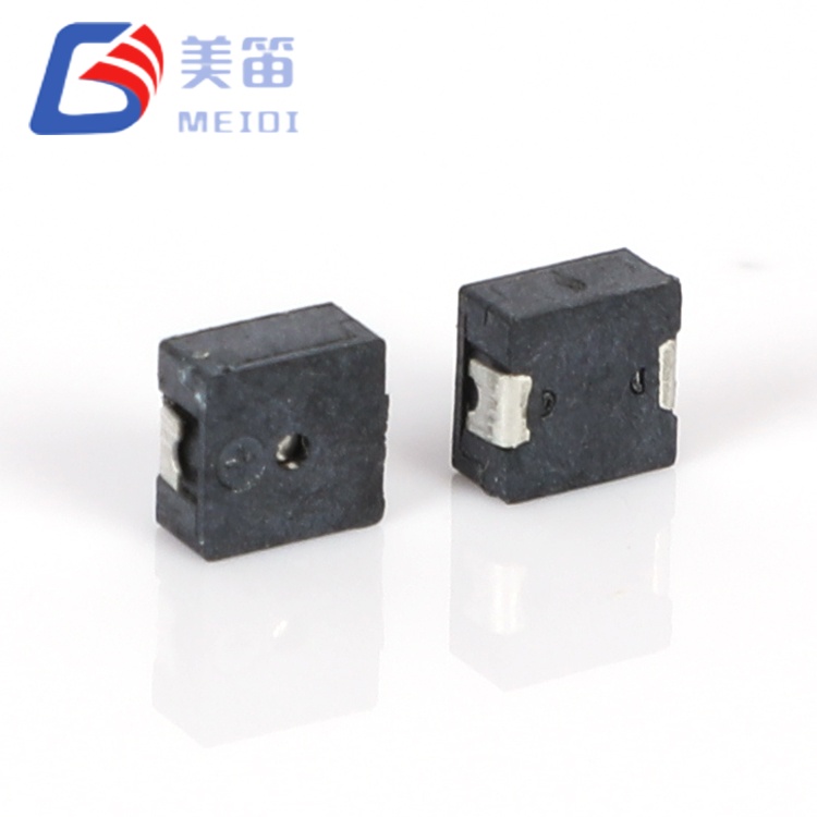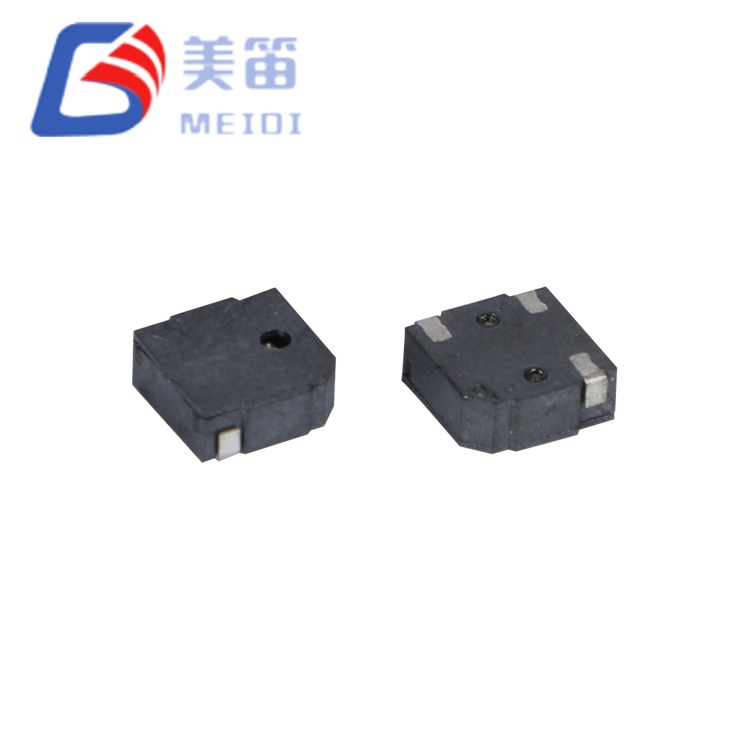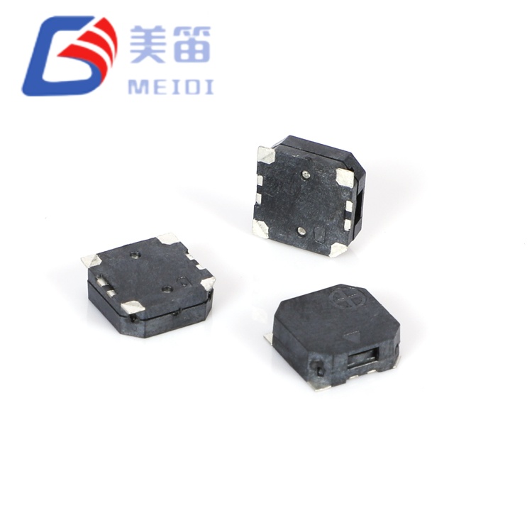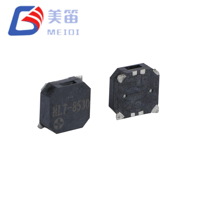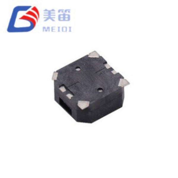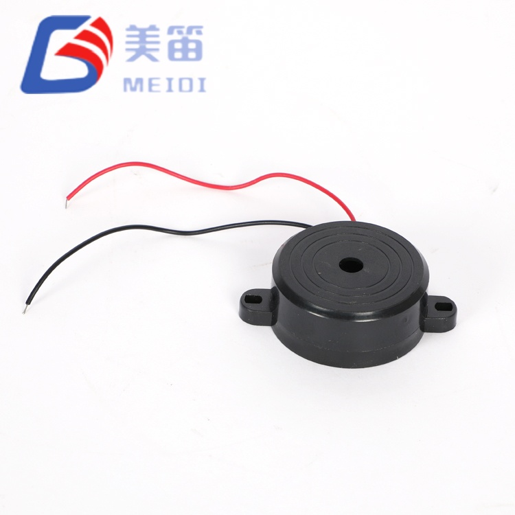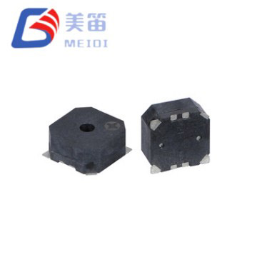
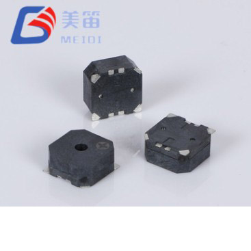
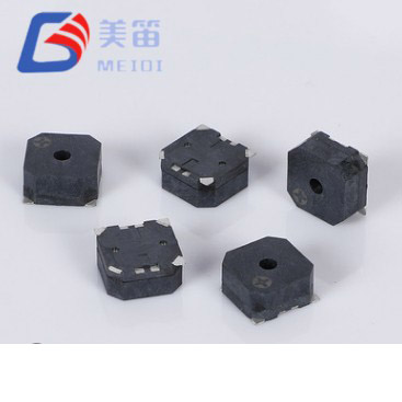
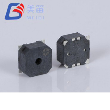
The 8.5*8.5*3mm SMD Magnetic Passive Buzzer delivers a practical solution for designs that require a surface‑mount electromagnetic buzzer with the flexibility to accommodate different supply rails on a single PCB footprint. Two impedance variants share the same 8.5 × 8.5 × 3.0 mm package: the 16 Ω version covers 2.5 V to 4.5 V systems, while the 32 Ω version is optimised for 4.5 V to 6.5 V operation. Because both have identical mechanical dimensions, engineers can evaluate voltage and current trade‑offs during prototyping without committing to separate board layouts or enclosure designs.
As passive transducers, the MLT‑8530H‑16R and MLT‑8530H‑32R require an external square‑wave or PWM signal to generate sound. This approach puts full control of frequency, duration and modulation patterns in the hands of the firmware team, making it possible to create distinctive alert sequences without changing hardware. The resonant frequency is set at 2700 ± 300 Hz, and both variants guarantee a minimum sound pressure level of 85 dB at 10 cm under their respective rated voltages.
The black LCP housing is compatible with standard lead‑free reflow soldering, and the 3.0 mm profile height allows placement in assemblies where vertical space is at a premium but acoustic performance cannot be sacrificed. The following sections detail the electrical characteristics, drive recommendations, reliability verification and selection guidance for integrating this series into industrial, security, building automation and portable equipment.
Two coil resistances from one mechanical design: 16 Ω for lower‑voltage applications and 32 Ω for standard 5 V rails.
External drive required. The passive electromagnetic structure expects an AC waveform, typically a 2700 Hz square wave, which provides the freedom to implement custom tone patterns, variable durations and multi‑tone alerts entirely through software.
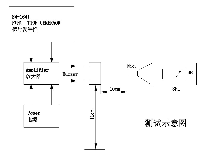
Guaranteed sound output of at least 85 dB at a 10 cm distance, measured at the rated voltage for each variant.
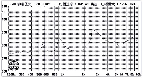
Resonant frequency 2700 ± 300 Hz, with batch sample data confirming a tight 2700 Hz centre across multiple units.
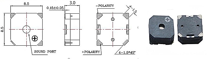
Compact 8.5 × 8.5 mm footprint and 3.0 mm height, designed for dense SMT assemblies where board area and clearance are both constrained.
Operating temperature range from −30 °C to +70 °C, supporting cold‑start conditions and outdoor enclosures.
Black LCP housing compatible with reflow soldering up to 255 ± 5 °C, as well as wave and manual processes.
| Parameter | MLT‑8530H‑16R | MLT‑8530H‑32R |
| Rated Voltage | 3.6 V (Vo‑p) | 5 V (Vo‑p) |
| Operating Voltage | 2.5 – 4.5 V (Vo‑p) | 4.5 – 6.5 V (Vo‑p) |
| Sound Output at 10 cm | ≥ 85 dB | ≥ 85 dB |
| Operating Current | ≤ 100 mA | ≤ 80 mA |
| Resonant Frequency | 2700 ± 300 Hz | 2700 ± 300 Hz |
| Coil Resistance | 16 ± 3 Ω | 32 ± 3 Ω |
| Operating Temperature | -30 °C ~ +70 °C | -30 °C ~ +70 °C |
| Storage Temperature | -40 °C ~ +85 °C | -40 °C ~ +85 °C |
| Dimensions (L × W × H) | 8.5 × 8.5 × 3.0 mm | 8.5 × 8.5 × 3.0 mm |
| Weight | 0.5 g | 0.5 g |
| Housing Material | Black LCP | Black LCP |
A single PCB land pattern accommodates both the 16 Ω and 32 Ω parts, enabling platform designs that can be populated according to the target system voltage without layout changes.
The passive drive architecture relies on an externally generated square wave, which allows the microcontroller to define tone frequency, repetition rate and pattern. There is no internal oscillator to constrain the acoustic behaviour.
Acoustic output is specified at a minimum of 85 dB for both variants, with a resonant frequency of 2700 Hz and a tolerance of ±300 Hz.
Current consumption is rated at ≤100 mA for the 16 Ω version at 3.6 V and ≤80 mA for the 32 Ω version at 5 V, providing clear figures for power supply sizing.
The 3.0 mm height keeps the component within the z‑envelope of many multi‑board systems, while the 8.5 mm square footprint preserves adjacent routing channels.
Continuous operation is specified from −30 °C, a lower limit that extends the usable range beyond what many commercial‑grade buzzers offer.
The black LCP package withstands reflow, wave and hand soldering profiles, giving manufacturers flexibility in assembly sequence.
| Parameter | Value | Test Conditions |
| Product Type | Electromagnetic SMD Passive Buzzer | — |
| Rated Voltage | 3.6 V (Vo‑p) | Nominal |
| Operating Voltage | 2.5 – 4.5 V (Vo‑p) | Continuous |
| Sound Output at 10 cm | ≥ 85 dB | At 3.6V, 10 cm |
| Operating Current | ≤ 100 mA | At 3.6V |
| Resonant Frequency | 2700 ± 300 Hz | At rated voltage |
| Coil Resistance | 16 ± 3 Ω | At 25 °C, DC |
| Operating Temperature | -30 °C ~ +70 °C | Continuous |
| Storage Temperature | -40 °C ~ +85 °C | Non‑operating |
| Dimensions (L × W × H) | 8.5 × 8.5 × 3.0 mm | Body only |
| Weight | 0.5 g | Typical |
| Housing Material | Black LCP | Reflow compatible |
| Parameter | Value | Test Conditions |
| Product Type | Electromagnetic SMD Passive Buzzer | — |
| Rated Voltage | 5 V (Vo‑p) | Nominal |
| Operating Voltage | 4.5 – 6.5 V (Vo‑p) | Continuous |
| Sound Output at 10 cm | ≥ 85 dB | At 5V, 10 cm |
| Operating Current | ≤ 80 mA | At 5V |
| Resonant Frequency | 2700 ± 300 Hz | At rated voltage |
| Coil Resistance | 32 ± 3 Ω | At 25 °C, DC |
| Operating Temperature | -30 °C ~ +70 °C | Continuous |
| Storage Temperature | -40 °C ~ +85 °C | Non‑operating |
| Dimensions (L × W × H) | 8.5 × 8.5 × 3.0 mm | Body only |
| Weight | 0.5 g | Typical |
| Housing Material | Black LCP | Reflow compatible |
| Variant | SPL Range (dB) | Current Range (mA) | Frequency (Hz) | Impedance Range (Ω) |
| MLT‑8530H‑16R | 89.9 – 92.5 | 68.6 – 72.5 | 2700 | 15.4 – 16.5 |
| MLT‑8530H‑32R | 90.1 – 92.4 | 59.6 – 63.1 | 2700 | 30.5 – 32.8 |
The measured values show the typical spread within a production batch. Guaranteed limits are listed in the individual specification tables above. Contact MEIDI for full batch test reports and process capability data.
| Variant | Recommended Driver | Typical Configuration | Remarks |
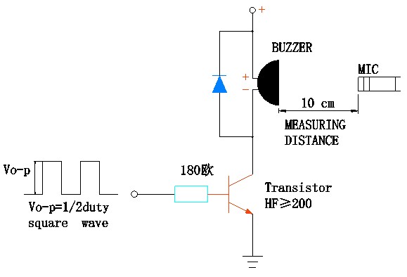
| MLT‑8530H‑16R | Transistor buffer | NPN transistor or logic‑level MOSFET with base/gate resistor | Direct GPIO drive is not feasible due to the current requirement; a switching element is necessary. |
| MLT‑8530H‑16R | Open‑collector driver | NPN with pull‑up to supply | Standard configuration; select base resistor according to transistor datasheet. |
| MLT‑8530H‑32R | Transistor buffer | NPN transistor or logic‑level MOSFET with base/gate resistor | Required; GPIO pins cannot supply the load current directly. |
| MLT‑8530H‑32R | Dedicated buzzer driver IC | Square‑wave output, 5 V capable | Ensure the output frequency is tuned to 2700 Hz for maximum sound pressure. |
| Both variants | Audio amplifier | Sine or square wave, output impedance matched to coil resistance | Useful when volume control or waveform purity is required. |
A 2700 Hz square wave with a 50 % duty cycle, at the rated peak‑to‑peak voltage, delivers the specified acoustic performance. Driving the buzzer at frequencies away from resonance will reduce the sound level and increase reactive loading.
The application notes below are based on the electrical and environmental specifications of the 8.5*8.5*3mm SMD Magnetic Passive Buzzer. They are not design guarantees; verify performance against your specific requirements and applicable standards.
Industrial automation panels: fault alarms and process status indicators in PLC and motor drive systems benefit from the dual‑impedance option, which aligns with both 3.3 V and 5 V control logic without board changes.
Security and access control: intrusion panels and card readers can generate distinctive PWM‑controlled alert rhythms, helping operators distinguish between different events.
Building and home automation: gateway hubs, smoke detector interconnects and thermostat confirmations rely on the buzzer’s ability to produce software‑defined notification patterns.
Battery‑powered instruments: the 16 Ω variant suits 3.3 V Li‑ion systems, while the 32 Ω variant is optimised for 5 V regulated supplies, covering a wide range of portable equipment.
Telecommunications infrastructure: cabinet intrusion and power‑failure alarms in outdoor or unheated locations benefit from the −30 °C lower operating limit.
Outdoor and thermally exposed enclosures: equipment subjected to wide temperature swings can depend on the specified −30 °C to +70 °C operating range for consistent alert generation.
| Design Requirement | MLT‑8530H Series Advantage |
| Platform voltage still to be confirmed | Common footprint allows a late swap between 16 Ω and 32 Ω, preserving the PCB layout. |
| Trade‑off between voltage headroom and current consumption | The 16 Ω version operates at lower voltages, while the 32 Ω version reduces current draw on 5 V rails. |
| Need for customisable alert patterns | Passive design hands full control of tone frequency, on‑off timing and modulation to the microcontroller. |
| Tight PCB real estate | 8.5 mm square body and 3.0 mm height fit dense SMT layouts. |
| Cold‑climate deployment | −30 °C operating floor is documented in the specification. |
| Mixed soldering processes | Reflow, wave and manual soldering are all covered by the product specification. |
The 8.5*8.5*3mm SMD Magnetic Passive Buzzer occupies a position between the smallest SMD buzzers and larger through‑hole types. The 3.0 mm height provides enough internal volume for robust acoustic output, while the shared footprint across two impedance values gives design teams the freedom to optimise the electrical interface late in the development cycle. The 2700 Hz resonant frequency, lower than the more common 4 kHz, may also be preferred in acoustic environments where a slightly deeper tone offers better discrimination.
Evaluation samples are available for both impedance variants so that you can confirm sound pressure, current consumption and drive compatibility on your own board.
MEIDI Intelligent Technology has been producing electromagnetic and piezoelectric acoustic components since 2011. The company’s vertically integrated factory in Jiangsu, China, combines in‑house LCP moulding, automated coil winding, SMD assembly and 100 % acoustic testing. ISO 9001 certification and a dedicated reliability laboratory provide the framework for consistent quality across high‑volume production. Customers in the automotive, industrial, security and consumer electronics sectors rely on MEIDI’s engineering support and on‑time delivery.
The MLT‑8530H series is manufactured under this same quality system. Every batch is subjected to a reliability verification programme that follows the product specification. Environmental stress screening consists of 48 hours at +80 ± 2 °C, 48 hours at −30 ± 2 °C, and five cycles of thermal shock between these extremes with a 30‑minute dwell at each temperature. Mechanical robustness is confirmed by vibration testing from 10 Hz to 55 Hz at 1.0 mm amplitude on all three axes, followed by three 75 cm free‑fall drops onto a 10 mm hardwood surface.
Humidity resistance is evaluated by exposing samples to 50 ± 5 °C at 90–95 % relative humidity for 48 hours, with a 2‑hour ambient recovery before measurement. Soldering integrity is validated by a 10‑second solder heat test at 250 ± 5 °C (component body 2.0 mm from the solder point) and by full reflow profiling. All test conditions, acceptance criteria and batch documentation are available for customer review. For projects requiring extended qualification, such as those governed by automotive or medical device standards, MEIDI’s quality team can discuss additional screening protocols.

1. How do I decide between the MLT‑8530H‑16R and the MLT‑8530H‑32R?
The choice depends on your available drive voltage and how much current your power supply can deliver. The 16 Ω part operates from 2.5 V to 4.5 V and is a natural fit for 3.3 V logic or single‑cell Li‑ion designs. The 32 Ω part works from 4.5 V to 6.5 V, matching standard 5 V rails and drawing less current for the same acoustic output. Because both share the same land pattern, you can evaluate one variant and later switch to the other without modifying the PCB.
2. What drive circuit should I use for each variant?
Both types require an external square wave at 2700 Hz and the rated voltage. A transistor buffer or logic‑level MOSFET is needed because the coil current (≤100 mA for the 16 Ω, ≤80 mA for the 32 Ω) exceeds the capability of most microcontroller GPIO pins. A simple NPN transistor with a base resistor is the most common solution. Dedicated buzzer driver ICs can also be used; ensure the output frequency is set to 2700 Hz to hit the resonance point.
3. Can I run the MLT‑8530H‑16R on a 5 V supply, or the 32 Ω version on 3.3 V?
Operating the 16 Ω variant above 4.5 V risks overheating the coil. The 32 Ω variant below 4.5 V will produce reduced sound output that may fall below the specified 85 dB minimum. If your system voltage is fixed and does not match the natural range of either part, MEIDI can suggest alternative models or discuss a small‑value series resistor for the 16 Ω version, though this will lower the sound pressure.
4. What is the significance of the 2700 Hz frequency compared to 4000 Hz buzzers?
The 2700 Hz centre frequency is lower than the 4 kHz typical of many compact SMD buzzers. Both sit within the band where human hearing is sensitive, but the lower pitch may be perceived as less shrill and can behave differently inside an enclosure. The best choice depends on the ambient noise spectrum and the type of alert differentiation your product needs. Prototype testing with both frequency ranges is recommended if the tonal quality is critical.
5. What do the sample measurement tables tell me?
The 10‑unit sample data shows the typical performance spread for sound pressure, current, frequency and impedance. These figures are informative only and do not replace the guaranteed limits: ≥85 dB, 2700 ± 300 Hz, and coil resistance within ±3 Ω of the nominal value. Production batch reports that document these parameters for every shipment are available upon request.
For impedance selection assistance, drive circuit reference designs, voltage‑specific acoustic measurements or OEM customisation discussions, send your requirements through the contact form. The MEIDI applications engineering team normally responds within one business day with technical documentation, sample availability and volume pricing.
MEIDI’s Jiangsu factory has been supplying electromagnetic and piezoelectric acoustic components to global customers for over a decade. In‑house LCP moulding, automated coil winding, SMD assembly and full acoustic test capability ensure consistent quality at the volumes demanded by industrial, automotive and consumer markets. ISO 9001 processes and a dedicated reliability laboratory underpin the performance data published for each product.
Address
No.6, Wenlin Road, Chenbao Town, Xinghua City, Jiangsu Province, China
Tel