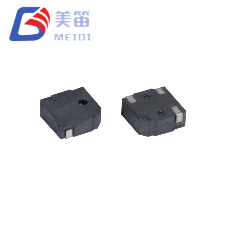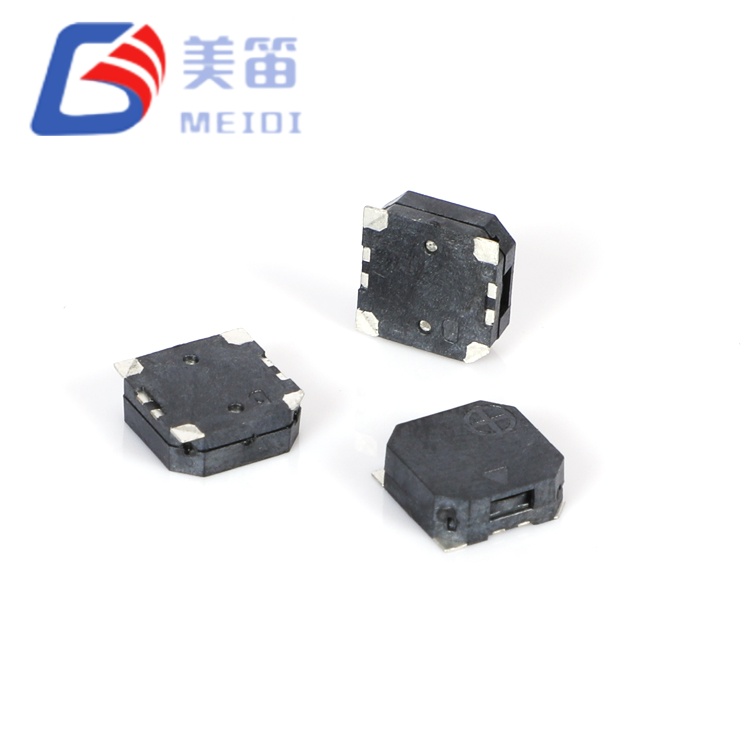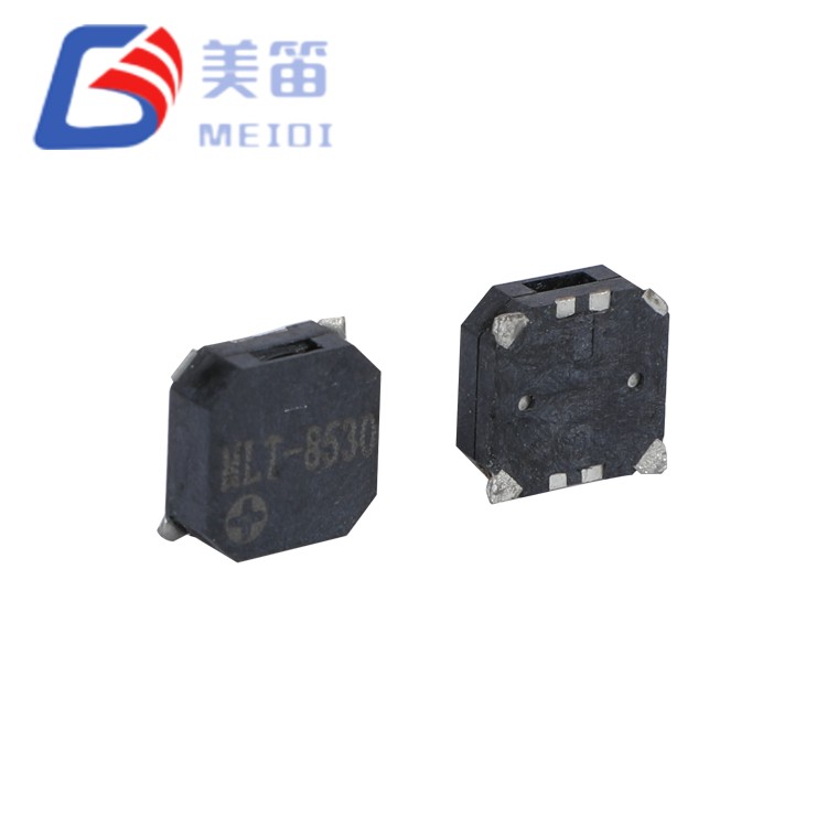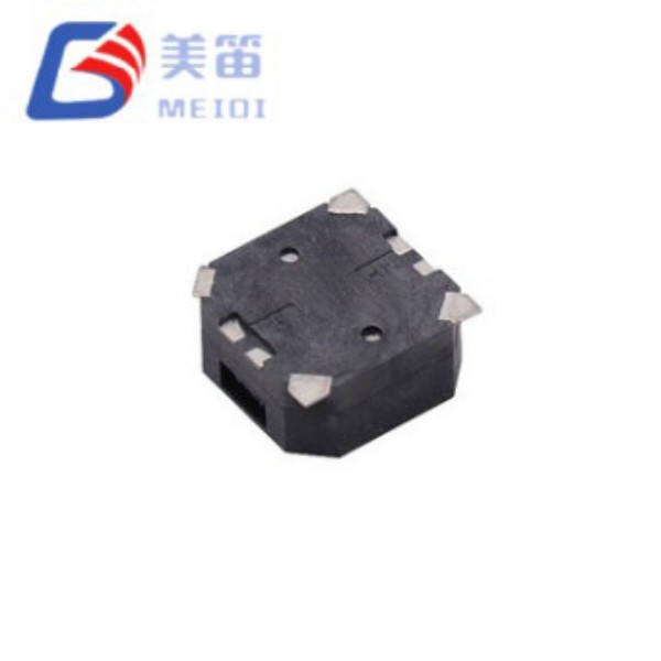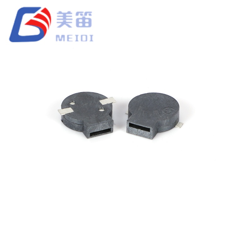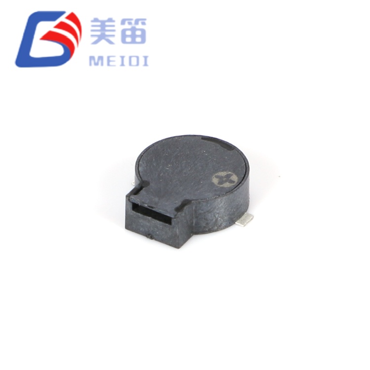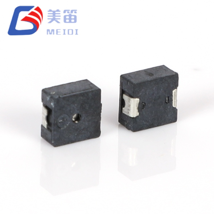
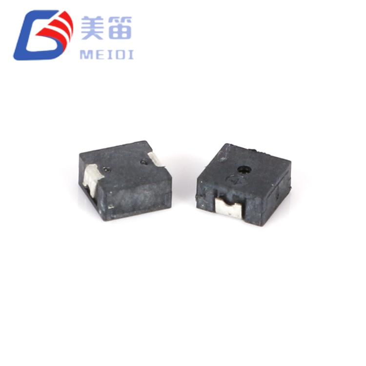
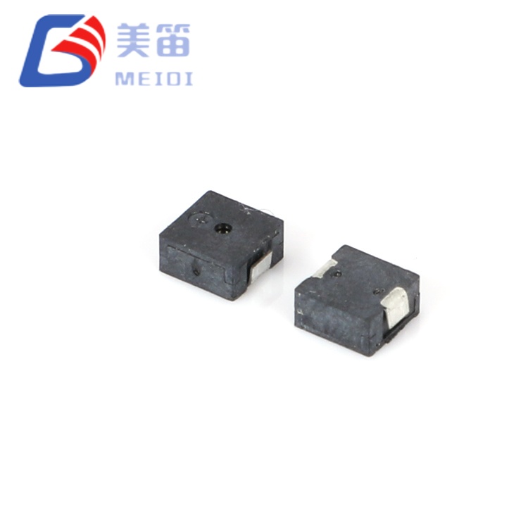
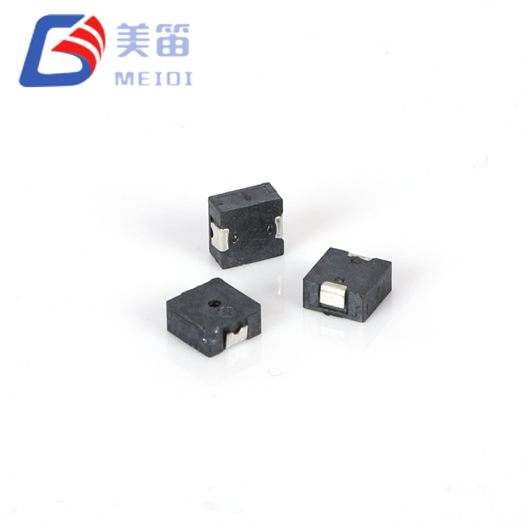
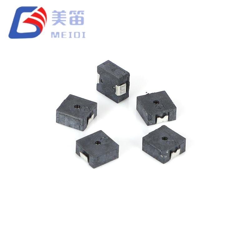
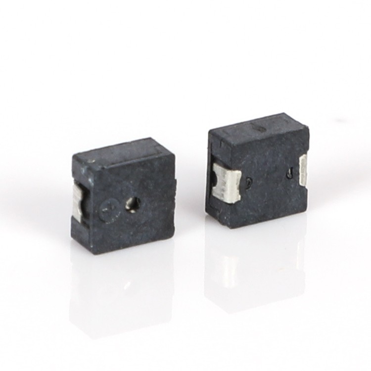
The MLT‑4020H is a 4*4*2mm SMD Magnetic Passive Buzzer engineered for high‑density PCB assemblies where every square millimetre matters. With a coil impedance of 12 ± 3 Ω and a resonant frequency of 4000 ± 300 Hz, this component delivers a minimum sound pressure level of 65 dB at 10 cm under 3.0 V square‑wave excitation, while drawing no more than 80 mA – a combination that makes it suitable for battery‑powered wearables, IoT sensors, and portable medical instruments.
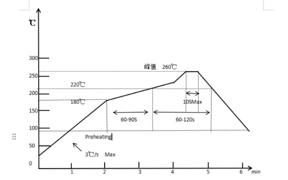
Manufactured at MEIDI’s ISO‑9001 certified facility, the MLT‑4020H benefits from automated winding, assembly, and testing processes that ensure consistent electrical and acoustic performance across production volumes. The black LCP housing withstands standard lead‑free reflow profiles with a peak temperature of 255 °C, enabling seamless integration into SMT assembly lines. Each unit is subjected to 100% impedance and frequency verification, with sample batch data confirming sound pressure levels consistently above 75 dB – providing substantial margin over the minimum specification.
The 4*4*2mm SMD Magnetic Passive Buzzer is a passive electromagnetic buzzer, requiring an external AC drive signal – typically a 4 kHz square wave or PWM output from a microcontroller – to generate audible alerts. This architecture gives designers full control over tone frequency, duty cycle, and pattern sequences, enabling priority‑coded alerts, melody generation, and volume modulation through simple software adjustments.
The 4 kHz resonant frequency falls within the 2–4 kHz band where human auditory sensitivity peaks, ensuring that even modest SPL levels are perceptible in typical indoor environments. The 12 Ω coil impedance is deliberately chosen to allow direct drive from standard 3.3 V and 5 V MCU GPIO pins, eliminating the need for external transistor buffers or dedicated driver ICs in many applications – provided the pin can source the ≤80 mA peak current.
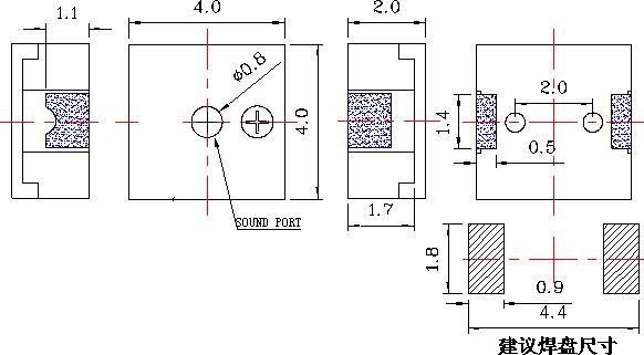
The ultra‑compact 4.0 × 4.0 mm footprint and 2.0 mm profile height are optimised for high‑density PCB layouts where vertical clearance is limited. At just 0.1 g, the component mass contributes negligible inertial loading, making it suitable for portable and wearable devices subject to shock and vibration. The LCP housing provides dimensional stability across the full ‑20 °C to +70 °C operating range and withstands the thermal stresses of reflow soldering without deformation or acoustic degradation.
Ultra‑miniature SMD form factor – 4.0 × 4.0 × 2.0 mm enables integration into space‑constrained designs without compromising acoustic performance
Optimised 4 kHz resonant frequency – centred in the human ear’s most sensitive range for maximum perceived loudness at minimal energy consumption
Low impedance coil (12 ± 3 Ω) – facilitates direct drive from low‑voltage MCU outputs, reducing BOM cost and circuit complexity
Wide 2–4 V operating window – compatible with single‑cell Li‑ion, 3 V coin‑cell, and standard 3.3 V logic rail supplies
High‑temperature LCP housing – withstands reflow soldering profiles up to 255 °C and maintains dimensional stability across ‑20 °C to +70 °C operating range
Reflow and wave soldering compatible – supports automated SMT assembly with up to 3 reflow passes, ensuring manufacturing flexibility
| Parameter | Value |
| Product Type | Electromagnetic SMD Passive Buzzer |
| Rated Voltage | 3.0 V (o‑p) |
| Operating Voltage | 2 – 4 V (o‑p) |
| Sound Output at 10 cm | ≥ 65 dB |
| Operating Current | ≤ 80 mA |
| Resonant Frequency | 4000 ± 300 Hz |
| Coil Resistance | 12 ± 3 Ω |
| Operating Temperature | -20 °C ~ +70 °C |
| Storage Temperature | -30 °C ~ +80 °C |
| Dimensions (L × W × H) | 4.0 × 4.0 × 2.0 mm |
| Weight | 0.1 g |
| Housing Material | Black LCP |
| Soldering Method (Recommended) | Reflow: 255 ± 5 °C, 3 s; Preheat 180 °C, 40–70 s |
Wearable health monitors – medication reminders and status alerts in compact fitness trackers and smartwatches where PCB area is extremely limited
IoT sensor nodes – low‑power acoustic feedback for environmental monitoring, smart agriculture, and asset tracking devices operating from coin cells or energy harvesting
Portable medical devices – audible confirmation tones in glucose meters, pulse oximeters, and handheld diagnostic instruments requiring compact, reliable audible indicators
Smart home controls – button press feedback and alarm notifications in thermostats, smart switches, and security keypads where space is constrained
Consumer electronics accessories – charging status and connection alerts in TWS earbuds cases, power banks, and Bluetooth tags
Light‑duty industrial handheld devices – scan confirmation and error alerts in compact barcode scanners, portable RFID readers, and mobile data collection terminals operating in controlled indoor environments
The MLT‑4020H delivers a measured sound pressure level of 75.6–79.7 dB (sample batch data), substantially exceeding the 65 dB minimum specification. This performance, achieved within a 4 mm square footprint and 2 mm height, results from optimised coil winding, magnetic circuit design, and diaphragm tuning. At 0.1 g, the component adds negligible mass to the PCB, an important consideration for wearable and portable devices where weight budgets are tightly controlled.
The 12 Ω coil resistance is selected to enable direct drive from standard GPIO pins without external buffering, provided the pin can source the ≤80 mA peak current – a capability common to many ARM Cortex‑M and other low‑power MCUs. For designs operating at 3.3 V, the buzzer remains within its 2–4 V operating range, delivering approximately 85% of the 3.0 V SPL while drawing slightly lower current. This voltage elasticity simplifies power supply design, as the same component can be used across product variants with different logic voltages.
For designers needing to meet tight acoustic specifications in space‑constrained applications, the MLT‑4020H provides a validated solution with full production traceability, documented test data, and compatibility with standard SMT assembly processes.
MEIDI manufactures the MLT‑4020H on dedicated SMD assembly lines featuring automated coil winding, soldering, and acoustic tuning. Our Jiangsu facility operates under ISO 9001:2015 quality management, with in‑process controls at every production stage – from material inspection to final functional testing.

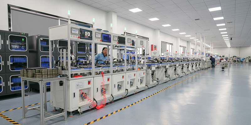
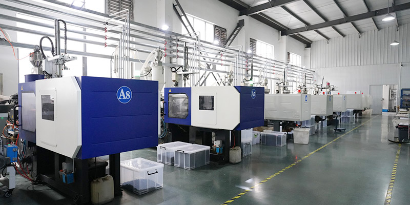
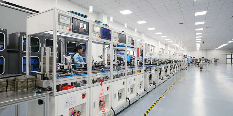
Each production batch is subjected to comprehensive qualification testing:
Acoustic verification – 100% SPL measurement at rated voltage; sample batch data shows 75.6–79.7 dB, consistently above the 65 dB minimum
Frequency stability – statistical sampling at 4000 Hz ±300 Hz; typical measured range 3950–4050 Hz
Coil resistance screening – 12 ± 3 Ω verification; measured values typically 11.2–12.8 Ω
High‑temperature storage – 48 hours at +80 ± 2 ℃; full parameter recovery after 2‑hour ambient stabilisation
Low‑temperature storage – 48 hours at -30 ± 2 ℃; verified activation at 2 V minimum
Thermal shock cycling – 5 cycles between -30 ℃ and +80 ℃ with 30‑minute dwell per extreme
Mechanical stress validation – sinusoidal vibration (10–55 Hz, 1.0 mm amplitude, XYZ axes, 0.5 hours cumulative) and 75 cm free‑fall drop onto 10 mm hardwood (3 impacts)
Humidity resistance – 48 hours at 50 ± 5 ℃ / 90–95% RH followed by 2‑hour recovery and electrical characterisation
Solder heat resistance – 250 ± 5 ℃ for 10 ± 0.5 seconds with 2.0 mm body‑to‑solder clearance, verifying LCP housing integrity
All components are RoHS and REACH compliant. Lot code markings on the housing enable full traceability to production date, test records, and material batch.
Q1: Does the MLT‑4020H require an external driver circuit?
Yes. As a passive electromagnetic buzzer, it requires an external AC signal – typically a 4 kHz square wave or PWM – to generate sound. Applying a steady DC voltage alone will not produce audible output. A standard microcontroller GPIO with PWM capability is sufficient for driving this unit, provided it can source at least 80 mA peak current. For GPIO‑limited designs, a small NPN transistor buffer can be added to handle the current load.
Q2: What is the recommended driving voltage and signal format?
The rated voltage is 3.0 V (peak‑to‑peak), with an operating range of 2–4 V. A 4 kHz square wave at 3.0 V provides optimal sound output. The 12 ± 3 Ω impedance allows direct drive from most 3.3 V MCU pins without additional amplification, provided the pin can source ≤ 80 mA. For 5 V systems, a series resistor (47–100 Ω) is recommended to limit current and prevent overheating, as the buzzer is not rated for continuous 5 V operation.
Q3: Is the MLT‑4020H compatible with standard SMT reflow processes?
Yes. The black LCP housing is rated for reflow soldering at 255 ± 5 °C peak for 3 seconds, with a 180 °C preheat stage of 40–70 seconds. Up to 3 reflow cycles are permitted without performance degradation. For wave soldering, parameters are 260 °C for 4–6 seconds. Manual soldering at 360 °C for 2–5 seconds is also supported. Always follow the recommended temperature profiles to avoid housing deformation or internal damage.
Q4: Can the sound frequency be adjusted, or is it fixed at 4 kHz?
While the resonant frequency is mechanically tuned to 4000 ± 300 Hz for maximum sound pressure, the buzzer will respond to drive signals across a broader frequency range. However, sound output diminishes significantly when driven far from resonance – approximately 6 dB per octave deviation. For variable‑tone applications, frequency modulation around 4 kHz (e.g., 3.5–4.5 kHz) is recommended to maintain adequate SPL while achieving tonal variation.
Q5: Are custom specifications available for OEM orders?
Yes. MEIDI supports OEM/ODM customization for volume orders. Options include alternative resonant frequencies (within 2–6 kHz), custom impedance values, specialised housing colours, and modified acoustic port configurations. Lead‑time and minimum order quantities depend on the scope of customisation. Contact our sales team to discuss your specific requirements, and we will provide a feasibility assessment and quotation.
Q6: What is the expected lifetime under continuous operation at 3 V?
The specified lifetime test condition is 96 hours at 25 ± 10 °C with a 1/2 duty‑cycle resonant‑frequency square wave. For continuous‑tone applications, MEIDI recommends limiting the duty cycle to 50% or implementing an intermittent alert pattern (e.g., 1 second on, 3 seconds off) to reduce coil heating and extend component life. Contact our engineering team for lifetime estimates under specific operating conditions.
For technical datasheets, reference designs, driver circuit examples, or volume pricing, contact MEIDI Engineering Support. We offer free engineering samples for qualified projects and provide responsive application assistance to streamline your integration.
Our applications engineering team typically responds within one business day with PCB footprint recommendations, reflow profile guidance, and design‑in support for your specific product requirements.
Address
No.6, Wenlin Road, Chenbao Town, Xinghua City, Jiangsu Province, China
Tel