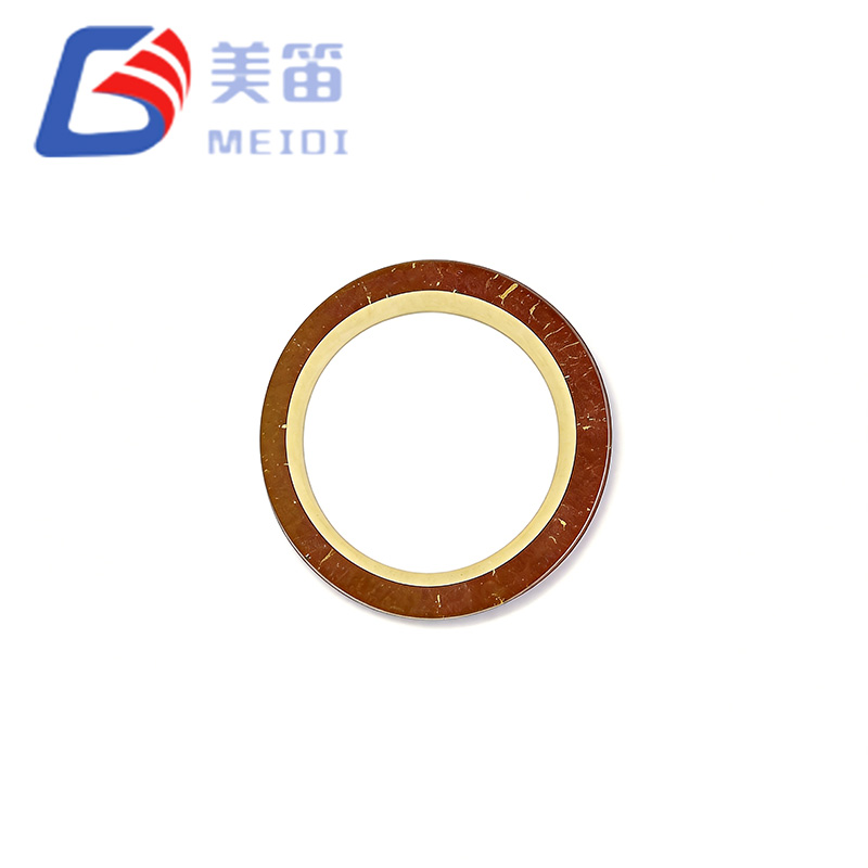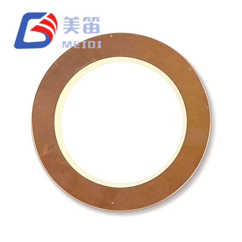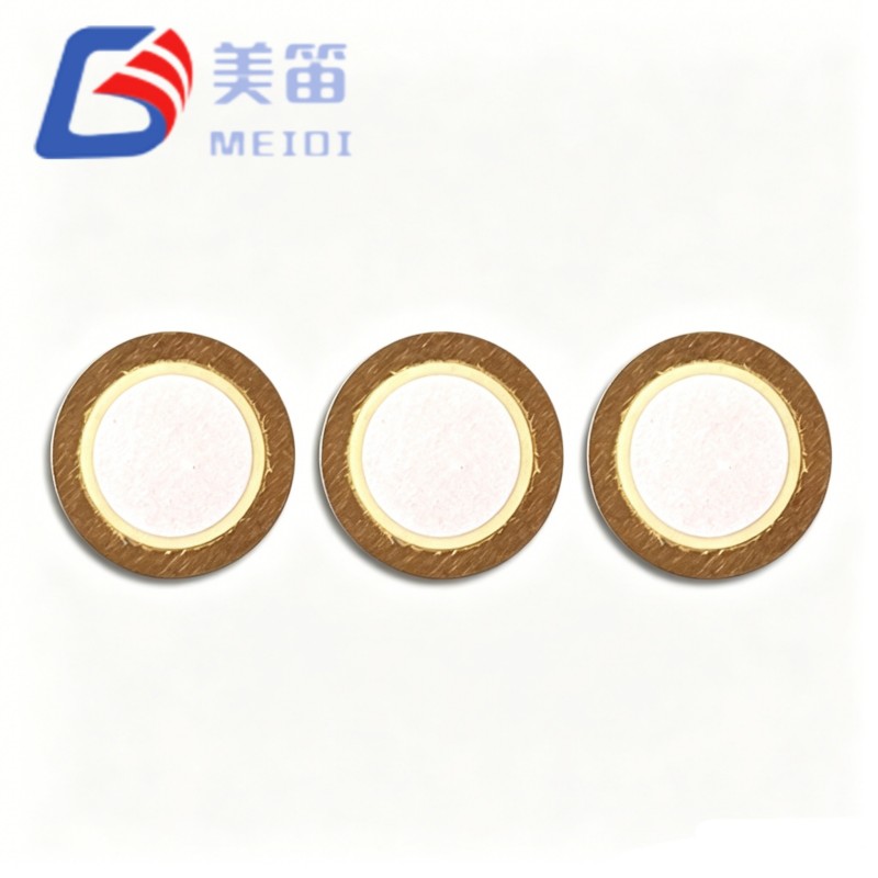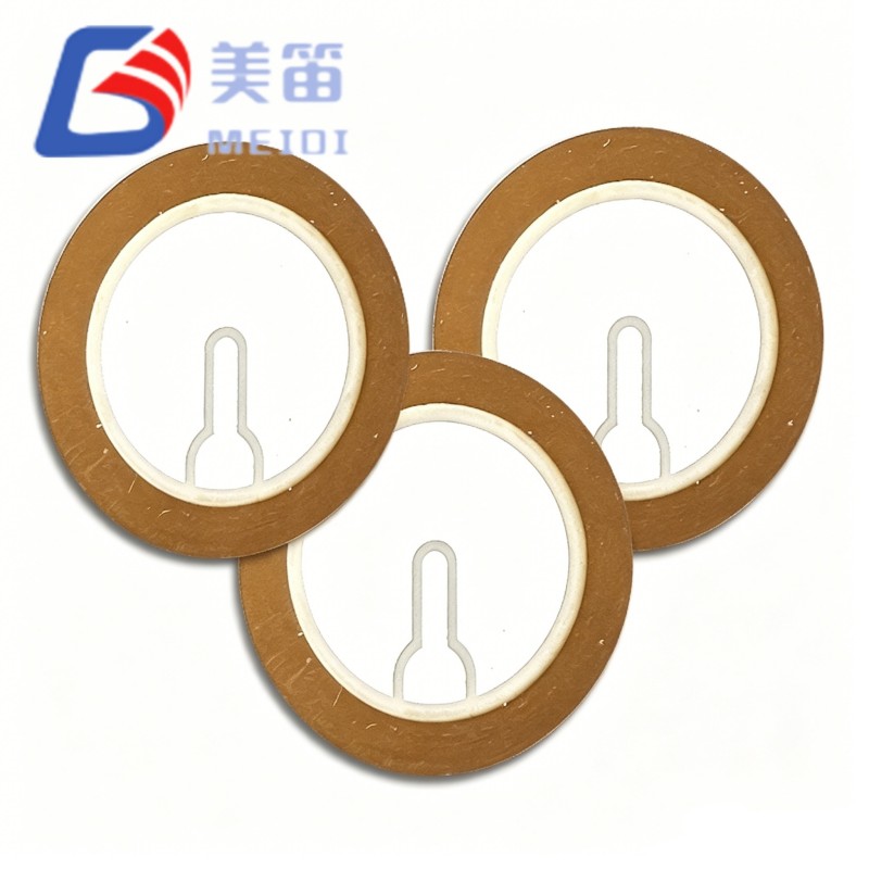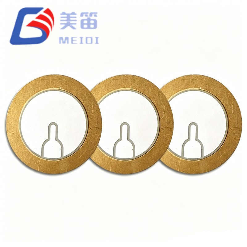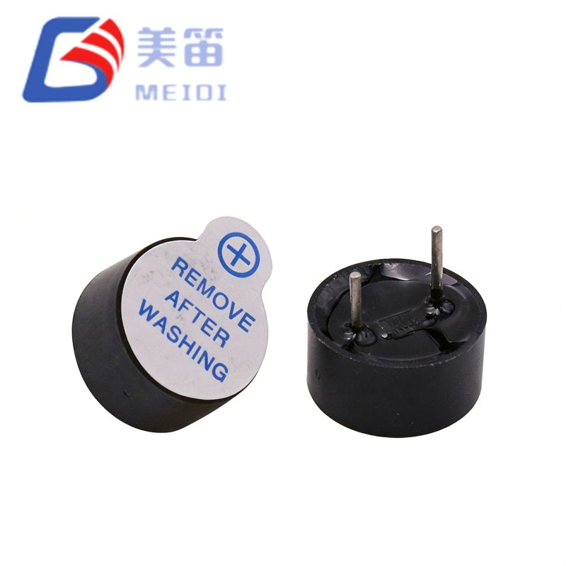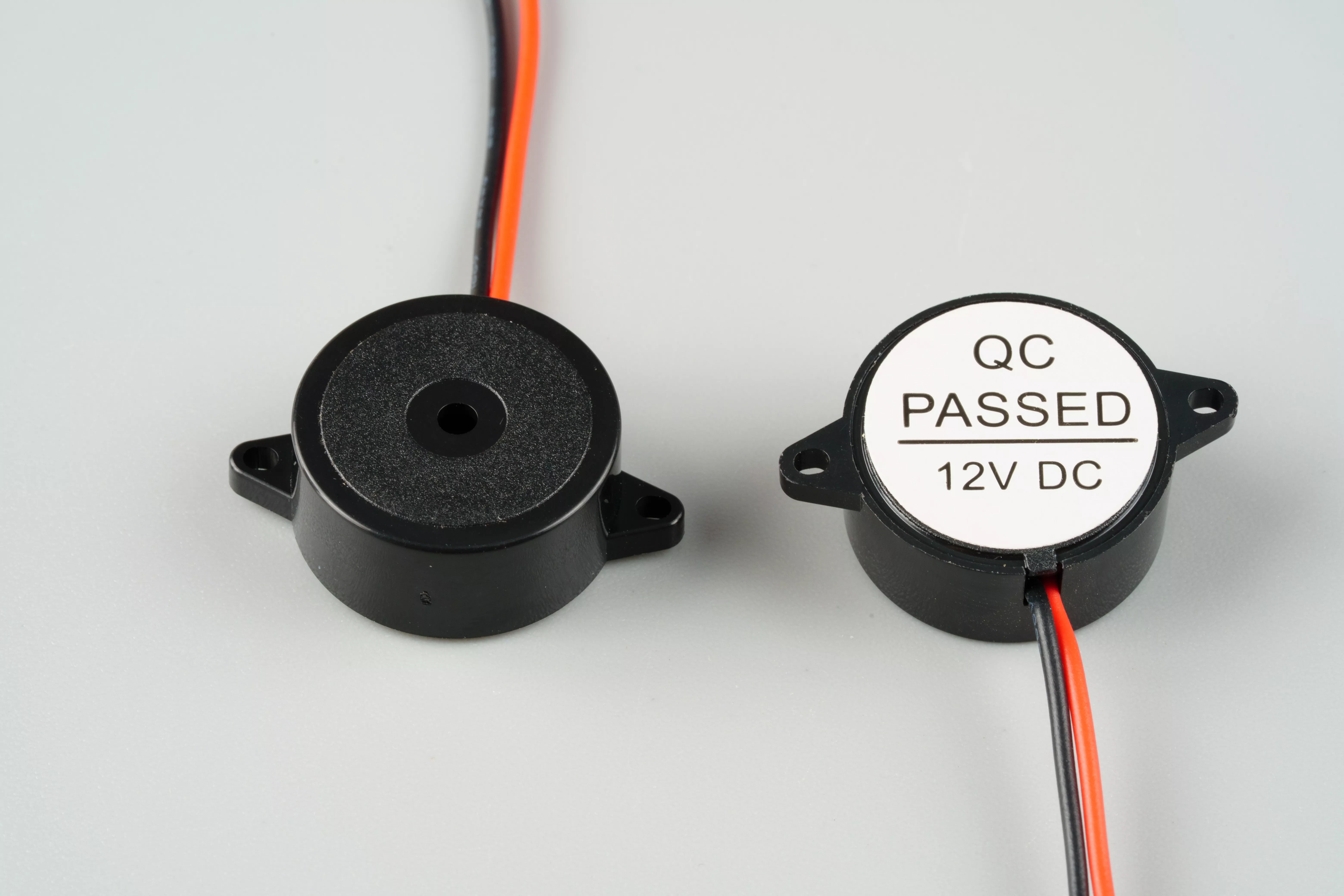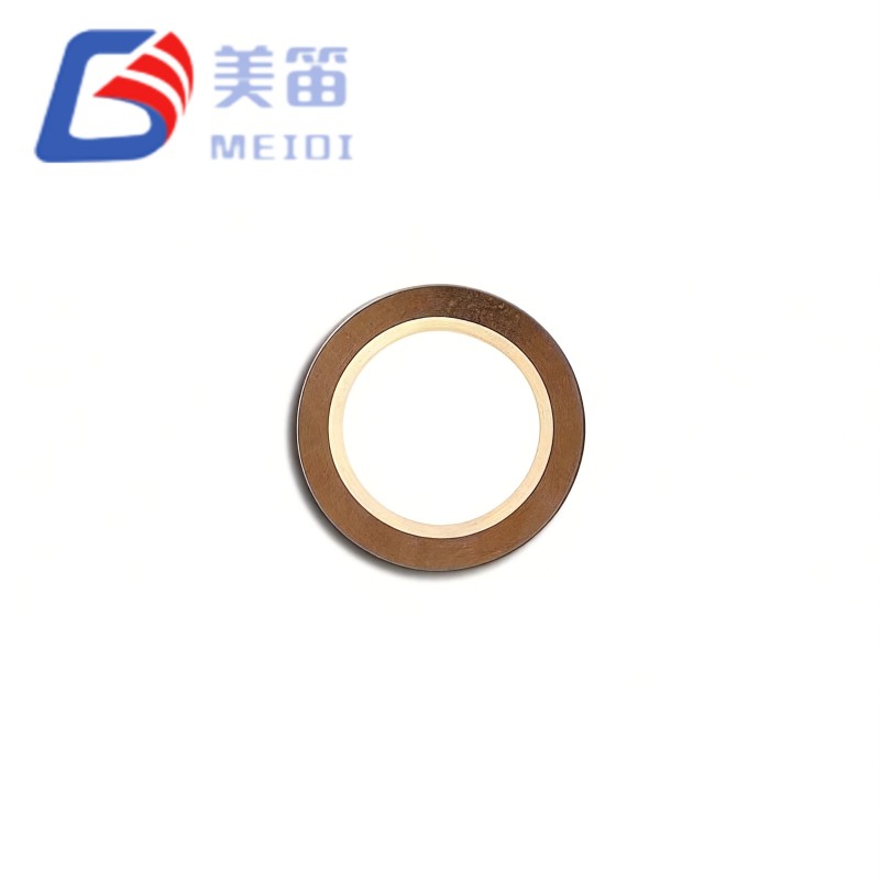
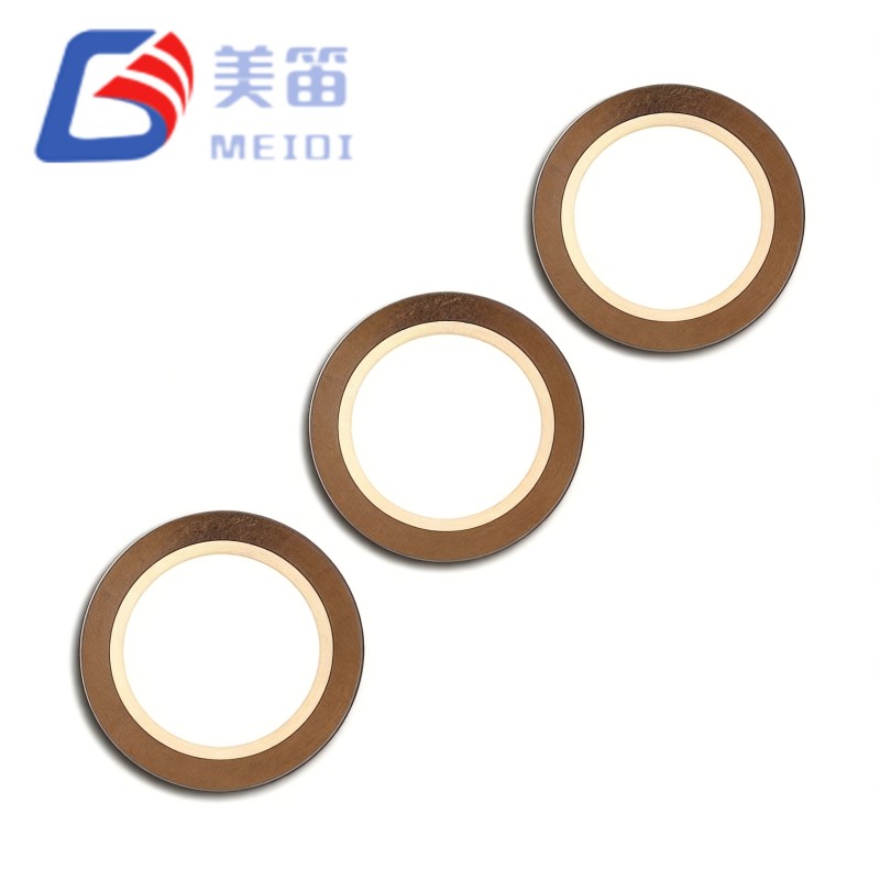
The12.5mm Piezo Ceramic Buzzer Element is a brass‑substrate piezoelectric ceramic element with a 12.5 mm active diameter, designed for embedded acoustic modules that require higher sound pressure from limited cavity volumes. Its resonant frequency of 7.8 kHz is held to a tight ±0.8 kHz tolerance, and the 12000 pF capacitance allows it to be driven directly from 3.3 V microcontroller pins or simple LC boost circuits. The element is built on the same manufacturing platform as MEIDI’s FT‑11T series, offering a straightforward upgrade path for designs that need increased acoustic output without reworking the electrical interface.
Active ceramic diameter of 12.5 mm provides a 29 % larger radiating area compared with the 11.0 mm FT‑11T family, contributing to higher displacement and improved low‑frequency response from small enclosures.
The resonant frequency is specified at 7.8 kHz with a tolerance of ±10.3 %, a tighter window than the ±12.8 % typical of the FT‑11T‑7.8A1, which helps maintain consistent tonal character across production batches.
A nominal capacitance of 12000 pF at 120 Hz presents a high capacitive load that is well suited to low‑voltage drive from 3.3 V MCU GPIO lines in battery‑powered embedded modules.
Equivalent resistance is specified at ≤300 Ω, which is 40 % lower than the ≤500 Ω of the FT‑11T series, enabling higher‑Q resonant boost topologies with greater voltage multiplication.
Total thickness is 0.19 mm, keeping the component within a sub‑0.2 mm profile that allows integration into ultra‑thin acoustic assemblies.
The brass substrate with a fired silver electrode follows the same material set used across the FT series, ensuring predictable thermal behaviour and solderability.
The enlarged 12.5 mm ceramic disc increases the active transduction area; the degree of acoustic improvement depends on the cavity design, diaphragm loading and the drive circuit, but the extra area provides a measurable advantage in compact modules.
Batch‑to‑batch frequency variation is limited to ±0.8 kHz, which supports multi‑element arrays and consumer product lines where uniform tonal quality is important.
The ≤300 Ω equivalent resistance reduces mechanical damping losses, allowing resonant boost circuits to achieve a higher Q factor and greater voltage gain from the same supply.
At 12000 pF the capacitance is identical to that of the FT‑11T‑7.8A1, so the same drive circuit topology can be reused when migrating to the larger diameter element.
The 0.19 mm total thickness, consisting of a 0.09 mm PZT layer on a brass diaphragm, enables sub‑1 mm acoustic module stacks and direct PCB bonding.
The active electrode diameter of 9.5 mm is proportionally scaled from the 9.0 mm electrode of the FT‑11T‑7.8A1, maintaining an optimal electric field distribution for the 7.8 kHz resonance.
| Parameter | Value | Test Conditions |
| Product Type | Piezoelectric Ceramic Element | — |
| Model | FT‑12.5T‑7.8A1 | — |
| Resonant Frequency | 7.8 ± 0.8 kHz | Free‑air, 25 ℃ |
| Frequency Tolerance | ±10.3 % | Batch consistency |
| Free Capacitance | 12000 ± 30% pF | At 120 Hz, 1Vrms, 25 ℃ |
| Equivalent Resistance | ≤ 300 Ω | At resonant frequency |
| Dielectric Loss (tanδ) | ≤ 5 % | At 120 Hz, 1Vrms |
| Substrate Material | Brass | — |
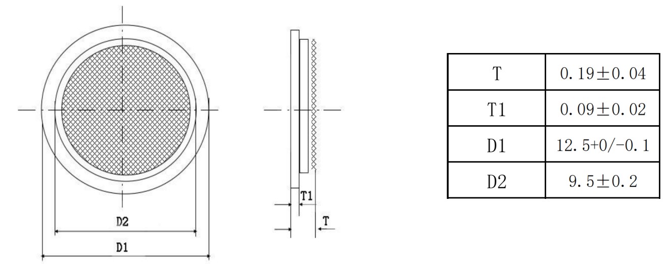
| Ceramic Disc Diameter (D1) | 12.5 +0 / -0.1 mm | — |
| Active Electrode Diameter (D2) | 9.5 ± 0.2 mm | — |
| Total Thickness (T) | 0.19 ± 0.04 mm | Ceramic + substrate |
| Ceramic Thickness (T1) | 0.09 ± 0.02 mm | PZT layer |
| Operating Temperature | -20 ℃ ~ +70 ℃ | Continuous |
| Storage Temperature | -30 ℃ ~ +80 ℃ | Non‑operating |
| Electrode Material | Silver (standard) | Fired silver paste |
| Insulation Resistance | ≥ 100 MΩ (typical) | At 100VDC, 25 ℃ |
Smart home devices such as video doorbells, smart speakers and thermostats benefit from the larger radiating area, which delivers a fuller tone from the compact internal cavities typical of these products.
Medical equipment acoustic modules, including infusion pumps, patient monitors and dialysis machines, rely on the tight frequency tolerance to produce a consistent alert tone across all manufactured units.
Industrial sensor panels and HMI terminals can use the lower equivalent resistance to obtain higher sound pressure from existing 24 V control circuit drivers without altering the drive stage components.
Automotive interior electronics, such as seatbelt reminders and EV charging indicators, can meet the required sound levels from smaller cavity volumes thanks to the increased diaphragm area.
Consumer appliances like washing machines and refrigerators can achieve the same acoustic output with a lower drive voltage, which may reduce the overall bill of materials.
Multi‑element acoustic arrays and synchronised notification systems benefit from the narrow frequency spread, which minimises perceptible beating and tonal inconsistency between adjacent units.
| Requirement | FT‑12.5T‑7.8A1 Attribute |
| Increased SPL from the same drive voltage | The 12.5 mm diameter provides a larger transduction area, which can raise the sound pressure by several decibels compared with an 11.0 mm element in an equivalent cavity. |
| Consistent tonal quality across production | The ±10.3 % frequency tolerance reduces unit‑to‑unit variation, supporting brand requirements for uniform product sound. |
| Efficient resonant boost | ≤300 Ω equivalent resistance allows LC boost circuits to achieve a higher multiplication factor, extracting more acoustic power from a low‑voltage rail. |
| Simple platform migration | The 12000 pF capacitance and 7.8 kHz resonance match the FT‑11T‑7.8A1, so only the PCB land pattern needs to be enlarged to accommodate the 12.5 mm diameter. |
| Richer low‑frequency character | The reduced stiffness‑per‑unit‑area of the larger ceramic disc improves sub‑resonant displacement, contributing to a perceptibly fuller tone in small enclosures. |
| Heat dissipation in sealed chambers | The 12.5 mm brass substrate provides a larger thermal interface, helping to stabilise the resonant frequency during continuous operation. |
The 12.5mm Piezo Ceramic Buzzer Element presents a 12000 pF capacitive load with a series resistance of 300 Ω or less at resonance. This combination supports resonant boost topologies where an inductor is placed in parallel with the element to form a high‑Q tank. Because the resistance is lower than that of the FT‑11T series, the achievable Q factor and voltage gain are higher; however, the circulating current also increases, so the inductor must be rated accordingly. MEIDI application engineers can provide reference designs and component recommendations for specific voltage and acoustic targets.
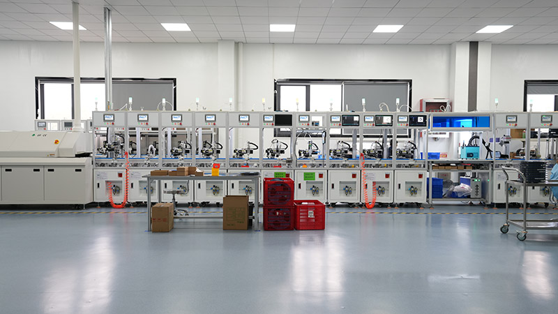
MEIDI Intelligent Technology has produced piezoelectric ceramic elements for over a decade. The company’s vertically integrated facility in Jiangsu, China, covers ceramic powder preparation, tape casting, screen printing of silver electrodes, high‑temperature sintering, polarisation and final electrical testing. An ISO 9001‑certified quality system and a dedicated reliability laboratory support the consistency and traceability of every batch.
The 12.5mm Piezo Ceramic Buzzer Element is manufactured with enhanced process controls to maintain the tight frequency tolerance and low equivalent resistance across the larger diameter. Each production lot undergoes 100 % resonant frequency measurement in a free‑air impedance analyser, with units falling outside the 7.8 ± 0.8 kHz window rejected. Equivalent resistance is screened at ≤300 Ω to identify electrode coverage defects or incomplete polarisation. Capacitance is verified at 120 Hz and 1 Vrms to confirm the 12000 pF nominal value within ±30 %, and dielectric loss is checked to ensure tanδ remains below 5 %. Dimensional inspection covers the ceramic diameter, electrode diameter and total thickness against the specification. Thermal ageing tests and solderability assessments are carried out on a sample basis. A lot code etched on the substrate edge provides full traceability to the pressing batch, sintering profile and individual test record, retained for ten years.

1. What performance gain can I expect when moving from the FT‑11T‑7.8A1 to the FT‑12.5T‑7.8A1?
The larger active area generally increases the acoustic output for a given drive voltage and cavity. The lower equivalent resistance allows resonant boost circuits to achieve a higher multiplication factor. The actual improvement depends on the enclosure, diaphragm and drive configuration; MEIDI can help evaluate the expected performance with your specific mechanical design.
2. Does the 12.5 mm element need a larger acoustic cavity than an 11.0 mm element?
A deeper cavity is usually beneficial when the element diameter is increased, as it provides better loading at the resonant frequency. The cavity diameter should also be larger than the ceramic disc to avoid clamping the radial vibration. For extremely compact designs, bonding the element to a thin metal plate that acts as a distributed radiator can be an alternative.
3. Why is the equivalent resistance lower than on the FT‑11T series?
The reduction comes from the larger electrode area and the optimised thickness of the PZT layer for the 12.5 mm format. A lower resistance improves the quality factor of resonant boost circuits but also increases the circulating current in the tank; the inductor should be sized to handle this higher current.
4. Can the FT‑12.5T‑7.8A1 be used alongside FT‑11T elements in a multi‑frequency array?
Yes, but the different diameters require separate PCB lands and cavity dimensions. When different resonant frequencies are driven simultaneously, audible beat frequencies may be produced. For clean dual‑tone operation, it is usually better to drive the elements sequentially or to select frequencies that are separated by at least 3 kHz. If phase coherence is needed, the different radiation impedances should be accounted for in the cavity design.
5. What PCB layout changes are needed to adopt the FT‑12.5T‑7.8A1?
The copper land under the ceramic disc should be enlarged from 11.0 mm to 12.5 mm, keeping the same annular ring width for solder or conductive epoxy attachment. A centre clearance hole, if used, should increase from approximately 3.0 mm to 4.0 mm. The component keep‑out area beneath the element should extend to a diameter of about 13.5 mm. The drive circuit component values can remain the same, but the inductor may need to be re‑evaluated to handle the higher circulating current in a boosted design.
For PCB integration layouts, cavity design recommendations for 12.5 mm elements, LC resonant boost circuit optimisation, migration support from the FT‑11T series, or volume pricing, send your requirements through the contact form. MEIDI application engineers typically respond within one business day with technical documentation, simulation models and sample evaluation units accompanied by individual test data.
Address
No.6, Wenlin Road, Chenbao Town, Xinghua City, Jiangsu Province, China
Tel